Contents
- Basics of UV light formation
- Masks for beam shaping
- Optical losses
- Excimer laser micromachining
- Procedures
I. Basics of UV light formation
Excimer lasers use a mixture of noble gases (Argon, Krypton or Xenon) and halogens (Fluorine, Chlorine or Bromine), both added in the order of several 0.1% in a Neon buffer gas. In given conditions of high pressure (several bars) and under electrical stimulation (in the kV range), the excited noble gas moves to an excited state that allows bonding with the halogen gas atoms. The bonding is temporary and the excited molecule quickly relaxes back to ground state. The excess of energy is given back as UV light emission.
A beam shaper converts the undefined mode structure of the emitted UV light into a top-hat beam profile, required for uniform materials machining.
II. Masks for beam shaping
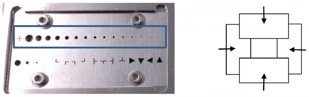
Excimer lasers generally have broad spatial profile beams and focal point applications are rare. Most processing is performed using projection optics, where the beam is used to illuminate a mask, whose demagnified image is then focused on the part to be machined. The final machining pattern on the part can be built up from repetition of selected motifs associated with part motion in X,Y and laser firing.
The mask may outline various 2D designs which are then projected as a whole onto the part. Multiple static masks may be mounted on a motorized selector carousel. Dynamic masks are possible by the use of motorized slits or apertures.
| Size on sample (um) | Size on sample (um) | |
| Mask Shape | Demag 10x | Demag 16x |
| Cross | 196×196 | 124×124 |
| Circle | 245 | 155 |
| Circle | 196 | 124 |
| Circle | 172 | 108 |
| Circle | 147 | 93 |
| Circle | 123 | 77 |
| Circle | 98 | 62 |
| Circle | 88 | 56 |
| Circle | 78 | 50 |
| Circle | 69 | 43 |
| Circle | 59 | 37 |
| Circle | 49 | 31 |
| Circle | 39 | 25 |
| Circle | 29 | 19 |
| Circle | 20 | 12 |
| Circle | 10 | 6 |
| Motorized Rectangular Aperture (MRA) | Max 300×300 | Max 190×190 |
III. Optical losses
Mirrors and lenses in the optical path have reflection and transmission losses. For ArF this can be something like 3-4% per optic, and also efficiency degrades with time, until eventually optics need replacing. The LSV3 optical path from the laser output bezel to the sample has in total 5 mirrors, 1 attenuator optic, 1 beam homogenizer optic and 4 lenses.
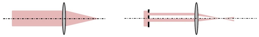
The beam has to fill the primary mask motif (beam shaping as describe above). Of course, in reality, the beam overfills the primary mask motif. This we can call geometrical transparency, which for a small motif can be very low. This geometrical loss is directly linear with the surface of the primary mask motif (see curves below).
For 193nm, ozone formation in air causes losses, which are usually estimated at 11% per meter path, but can be more than that in enclosed spaces if ozone is allowed to accumulate.
On the LSV3 system, the beam path is flushed with dry nitrogen to limit such losses. But in practice, it is impossible to totally close the beam path.
Of the energy present at the laser output bezel, a part is spontaneous emission rather than real stimulated emission, and has very high divergence. Several percent of the beam energy measured by the laser energy monitor is lost in this way.
Also, the energy indicated by the laser energy monitor is a guide. Indeed, it does happen that in time, airborne hydrocarbons are ‘cracked’ by the UV and form a thin graphite layer on the optics, which takes a sample of the beam to monitor the energy. The reflectivity of that sampler plate is nominally 5% (back face is AR coated), so 95% of the beam transmitted. With the graphite, the reflectivity of the upstream face can increase so less energy is transmitted. For this reason, it is important to regularly measure the real energy at laser output using an energy meter, to perform mirrors cleaning and/or replacement when needed.
IV. Excimer laser micromachining
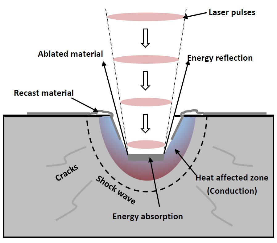
Two main mechanisms may occur during the UV laser ablation process of a material:
– In case of polymers machining, photo-chemical ablation is the predominant mechanism, where intermolecular bonds within the material are broken upon absorption of the laser energy. Material is removed without thermal effect. The penetration depth of the laser energy is inversely proportional to the absorption coefficient of the material at the given wavelength.
– Excimer machining may also involve a photo-thermal mechanism, where the laser energy is transferred within the material by conduction and converts into lattice vibration, resulting in melting and/or vaporization of the material. It is therefore dependent on the thermal diffusivity of the material. A short wavelength and short ns pulse duration allow to minimizing this thermal effect.
Part of the pulse energy may also be reflected at the sample surface. It occurs according to the reflectance of the material at the given wavelength and according to the surface finish, which may change during the ablation process.
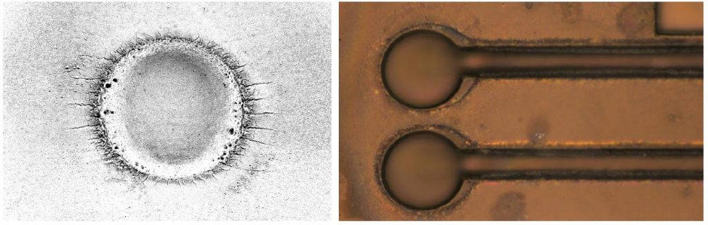
Depending on the predominant mechanism, small residues may redeposit around the ablation zone. A post-cleaning of the substrate with e.g. a sonication bath helps to clean.
Needed energy densities are typically in the range of 1-10J/cm2 at repetition rates up to several hundred Hz. Machining etch rates generally reach tenths of μm/shot.