In order to fabricate more complex micro/nano-devices, it is often necessary to perform multiple lithographic and processing steps requiring a careful alignment of subsequent layers. The ebeam tool enables his using a simple yet flexible alignment scheme and procedure. The alignment can be performed either manually to any visible feature on the surface of the wafer or chip, or in a fully automatic mode to well defined and fabricated alignment marks. The minimum required number of marks is 3 and the only restrictions on their placement is that they cannot be placed in a single line. But users are welcome to create also complex alignment schemes, with multiple (any number) alignment steps with markers placed as far or as close to their structures of interest as needed. Alignment procedure can also be used to simply reduce the influence of a drift during long jobs by scheduling the re-alignment to happen every so often and thus re-setting the coordinate system.
Alignment markers creation
There are in principle two way, how markers can be created. Users lucky enough to have a processing step after their first ebeam level lithography be identical to a processing step required to fabricate good markers (e.g. 100nm of gold deposition) can simply add marker patterns to their first level design, and they obtain their markers essentially “for free”. More common situation is that the markers have to be created first, using a “zero level” lithography step.
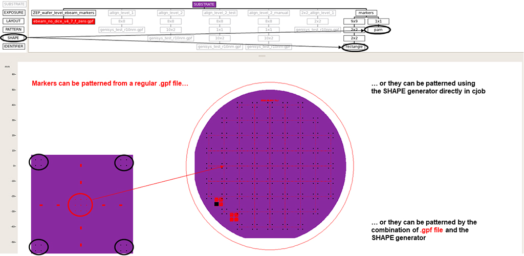
The marker patterns can be generated as a standard .gpf pattern file and printed as such, or they can be generated directly inside of the cjob software using the SHAPE option in the menu on the left side. Both approaches can also be combined in a single patterning step .
There are several types of markers that can be generated and used. It is recommended to use a simple square marker, 20×20μm in size. Typically, user would want to place more than one marker into any single location on the chip/wafer for several reasons. In case the marker is damaged, user can simply use a different one. Every marker that is actually used for alignment will get damaged during the subsequent processing step (as the resist around it is exposed during the marker search process, and thus it will be developed, exposing the marker to the etching/deposition step). So in a subsequent lithography step, different marker has to be used than before.
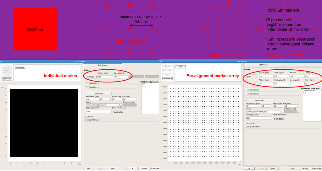
The individual markers should not be placed closer than 250μm. The search radius that is defined for the tool during the marker search operation is currently set to 40μm. Placing adjacent markers too close to one another creates a risk of a wrong marker being grabbed by the tool during the alignment procedure, which would of course generate a sizable image placement error.
40μm is not a very large distance when measuring the location of a first marker on the alignment microscope. To maximize a chance of the automatic procedure in the ebeam tool to actually finding the first marker that user specifies, special type of marker has been created – so called pre-alignment marker array. It consists of 10x10mm markers arranged in a grid, where the nearest neighbors distance in the center is 75,75μm, and this distance is increased by 1,1μm in every subsequent row or column away from the center. Thus the tool is always guaranteed to find some marker within the 40μm search radius, and from that marker find its way to the center of the pre-alignment marker array. It is not necessary to use these arrays at all, but they can help to make the process of finding the first marker more robust. The easiest way to generate these arrays is within the cjob.
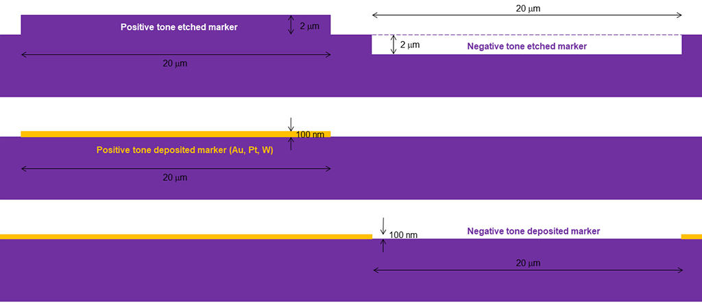
In order for a marker to be “visible” to a 100kV electrons, they need to be either exhibit a sufficiently high vertical surface topography, or they need to have a sufficiently high material (atomic number) contrast. If etching the markers into the same material (e.g. silicon wafer), the topography height variation needs to be at least 2μm. If the markers are made out heavy metal (Pt, Au, W), 100nm thickness should be sufficient to achieve good contrast for the pattern recognition algorithm. Positive tone markers are markers that will appear brighter than the background wafer/chip surface, negative tone marker are markers that will appear darker than the surrounding surface.
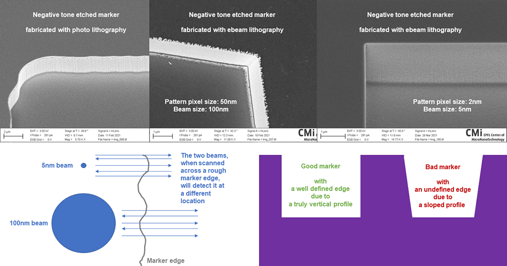
It is not necessary to fabricate markers using the ebeam litho. Given their size, standard photolithographic techniques, including mask aligner, can be sufficient. However, one needs to be aware of the impact marker quality will have on the alignment accuracy. Too much corner rounding or too large size difference from expected value may result in a failed marker search due to a pattern recognition failure. 30nm line-edge roughness will likely not allow alignment accuracy to better than 30nm, as the marker edge will not be detected at the same location during each marker search.
It is not only lithography that plays a role. Etching is also critical, and vertical side-wall for the etched markers is paramount. Having a 30nm edge slope (not much over the 2μm height) will produce a 30nm uncertainty of the edge placement, as the edge will appear not as a sharp edge from the top, but rather a gray-scaled gradient. If the gradient is too wide, the marker search will also fail.
The SEM micrographs (courtesy of Mohsen Bahramipanah and LSPR) illustrate the effect of the litho parameters at the edge quality. Anyone with stringent requirements for the utmost overlay accuracy should seriously consider using the finest pixel and small beam combination to define the marker edge as well as it can be done. Sub 10nm overlays have been achieved using this approach.
Setting up an alignment job
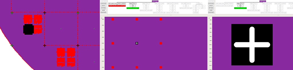
Inside of the cjob, the location of an alignment mark that user has placed is indicated with a small black cross. After zooming in, the cross turns white, and it is placed on the top of a black square that matches the exact size of the specified marker. In case of local alignment being deployed, the markers are shown in the same color as the patterns that are defined as aligned to them. In order to verify overlay with the previous litho level, it is customary to keep both the previous level and the new level shown in the cjob.
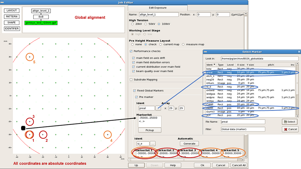
To setup a job as “an alignment job”, one starts with the global alignment. This is done at the EXPOSURE layer in the cjob. Select “Fixed Global Markers” and tick “Pre marker”. The “Pre marker” is the marker the location of which you measured on the alignment microscope prior to loading the wafer into the ebeam tool, and the coordinates you measured are the ones you enter into the batch_job script. The ebeam tool will match those coordinates with the cjob coordinates you specify for the “Pre marker”. This allows the OFFSET to be established.
Next you enter the location of the first 3 markers (in red color in the picture). They are not allowed to lay in a straight line, typical layout is a 90deg triangle. With these markers the tool can establish SCALE and ROTATION correction in both X and Y axis.
Optionally, one can further improve the accuracy of the correction with a use of markers 4 and 5 that would typically be placed at a larger distance. Using the trio 1,4,5 and the initial map already established with markers 1,2,3, the tool will fine tune that initial map, and it will have a higher chance of success even in case of slightly larger rotation, that would otherwise fail, as the markers 4 and 5 would be much more likely to fall outside of the 40mm search radius.
It is very important to minimize wafer or chip rotation when loading them onto the holder. Small adjustments to rotation can be done using the rotation screw present on each holder (see this web section about holders).
For the “Ident” field, user must choose a marker type from the existing list. While there are many different markers on the list, only 5 of them should be used:
preal – negative tone, rectangle, 10x10mm, array, 75,75μm spacing, 1,1μm increment
si_e – negative tone, rectangle, 20×20μm
PAMM – positive tone, rectangle, 10×10μm, array, 75,75μm spacing, 1,1μm increment
CAMP – positive tone, rectangle, 20×20μm
JOY – manual alignment
All coordinates specified for global alignment are absolute cjob coordinates. It is possible to use the exact same marker for both the “Pre marker” and “Marker 1”.
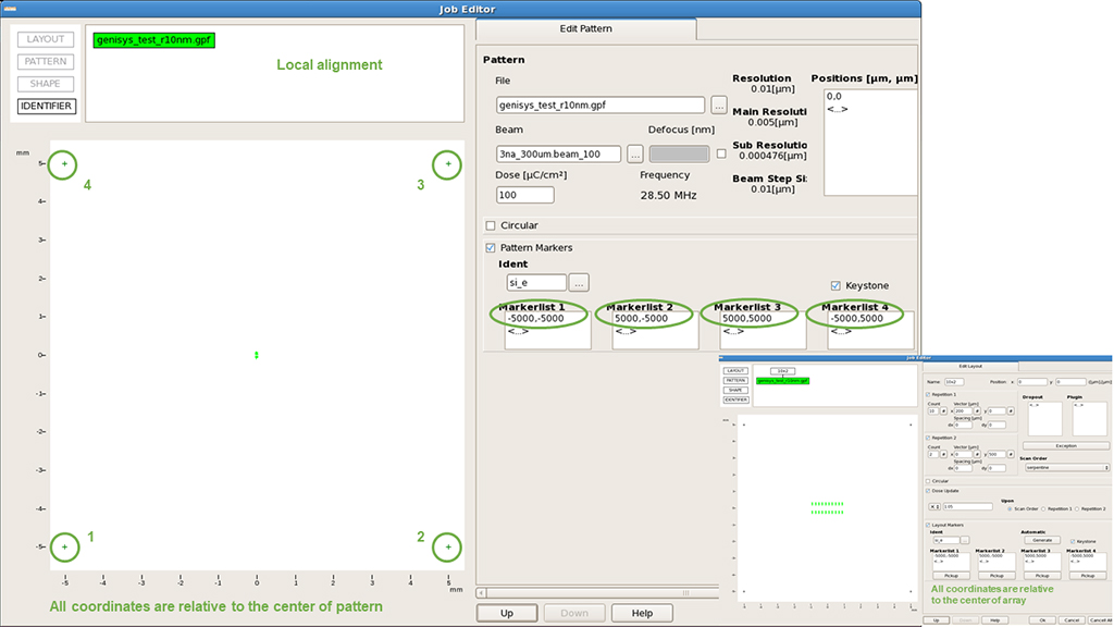
Local alignment is optional, and can be specified at any level below the EXPOSURE level. Typically, it is done at the PATTERN or LAYOUT level. At the PATTERN level the markers will be shown with the same color as the pattern. At the LAYOUT level, they will be black. Local alignment coordinates are specified relative to the center of pattern or pattern array. 4th marker can be added to the standard 3, and this enables the tool to also perform KEYSTONE correction that corrects for the small tilt that can be present in the sample.
IMPORTANT: If the search for a global marker fails, the tool will abort the job before writing a single pixel. If the local marker search fails, the writing of a job will continue, and the global map will be used. Typical successful automatic marker search takes about 2 seconds per marker. Unsuccessful search will abort each marker search after about 8 seconds. These times are not included in the cjob time estimation, and users needs to add them manually when planning tool booking for their jobs.
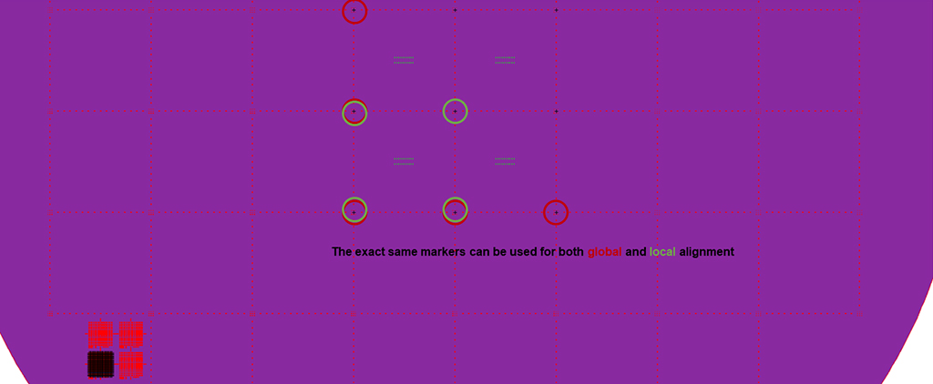
The exact same markers can be used for both the global and local alignment.
Manual Alignment
It is possible to perform the alignment manually. This is a very empowering option, as it gives a user chance to align literally to any feature on the wafer that is discernible with the 100kV SEM.
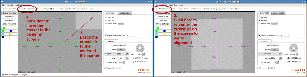
To perform manual alignment, specify marker type as JOY. The tool will move the wafer and beam to the specified location and ask you to confirm the location. Turn ON the SEM. If a marker is visible somewhere in the window, simply drag the crosshair to the center of the marker. Click “move to crosshair” in the top menu. Click “center crosshair” to return the crosshair to its original position. If the crosshair does not land exactly in the center of the marker, simply repeat the above steps until it does. You should do all of this at 5000 magnification to minimize the nm/pixel error. When satisfied with the position, simply confirm the location to the tool by clicking “enter” in the main job window, where you were asked to confirm the marker location.
The accuracy of the manual alignment is only as good as the skill of the operator, and typically somewhere around several hundred nm or 1-2μm. Thus, there is no need to set up any local alignment for jobs with manual alignment scheme, as there would be no improvement being made.