To be read first:
- For DUV lithography process steps with the TEL ACT-8 track, CMi recommends to use wafers with the lowest possible total thickness variation (TTV<2 μm) to reduce the impact of of high local thickness variations.
- Wafers going through the track must have a clean backside. Immediately remove wafers with a contaminated or dirty backside from your batch! Small particles, although not visible by eye, can hinder printing of small features and/or contaminate wafer stage for the next batches. Wafer stage cleaning is a delicate and complex operation which is wearing, time-consuming, and needs re-calibration. Users liable of wafer stage contamination will be billed cleaning hours and may loose access to the machine.
RESERVATION RULES AND BOOKING FEES POLICY:
- Booking: No booking (CMi service).
- Billing: 15 minutes + processing time.
Contents:
- Introduction
- Equipment description
- Process
- Links
- Pictures gallery
I. Introduction
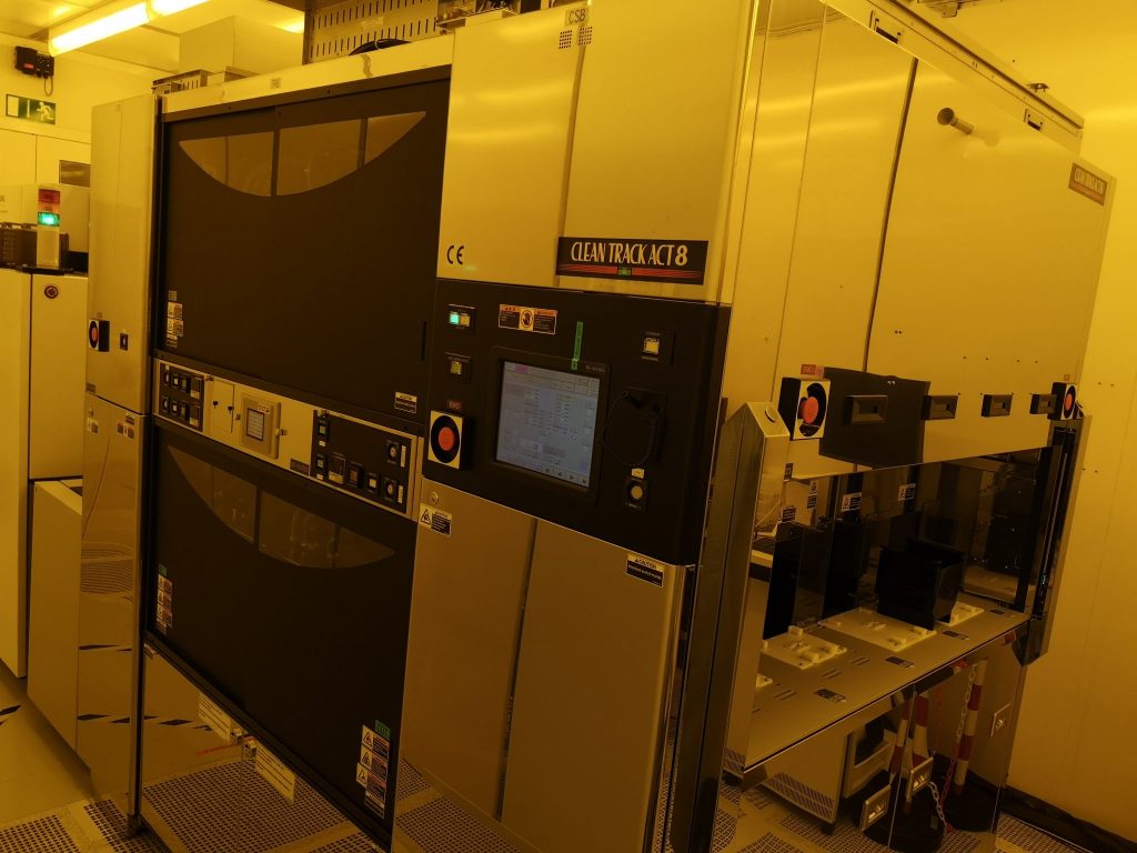
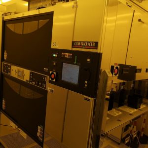
The Clean Track ACT8 is an industry-standard wafer coater and developer. It supports lithography at high throughput in a small footprint, enabling DUV lithography with an in-line exposure unit interface, ULPA chemical filters, and high-precision ovens.
II. Equipment description
The ACT8 in CMi is a coater and developer track in-line with the ASML PAS5500/350C stepper to form a DUV lithography cluster. The cluster is configured for 100 mm (4″) wafers.
Conversion to 150 mm (6″) is possible, but since it requires some mechanical work on the track and must be followed by an extensive setup on the stepper, it is performed rarely and on-demand.
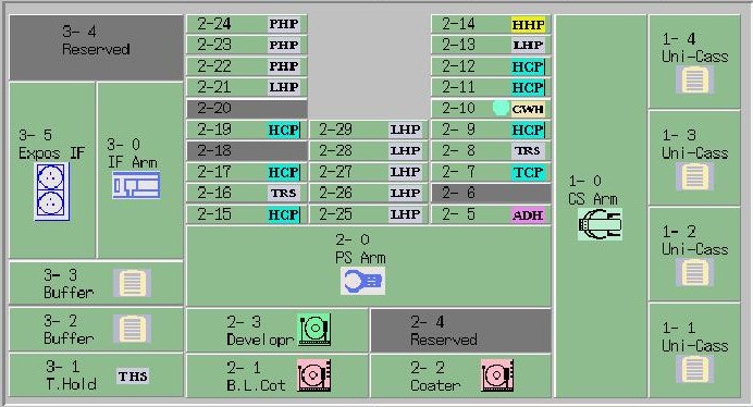
The tool is composed by three main blocks: Carrier Station Block (CSB, modules 1-*), PRocess Block (PRB, modules 2-*), and InterFace Block (IFB, modules 3-*).
a. Carrier Station Block
CSB is the interface with the external world. It features four cassette ports, two for 100 mm wafers (Uni-Cass, 1-1 and 1-2) and two for 150 mm wafers (1-3 and 1-4). The Carrier Robot Arm (CRA, 1-0) shuttles wafers between cassettes and PRB via pass-through module (accessible by the robot of next block) which consists of two stacked units:
- TRansition Station (TRS, 2-8): wafer input from cassettes.
- Transition Chill Plate (TCP, 2-7): wafer output to cassettes. This plate is passively chilled by fab Process Cooling Water (PCW).
When a cassette is loaded, CRA automatically scans it with a through-beam detection system to determine present wafers.
- Use CMi “black” cassettes only (from Entegris). Other cassettes may either not fit the loading port base or have different dimensions/pitch, putting CRA (and your wafers) in serious danger.
- Put flats at the back of the cassette(s) when transferring wafers (use the flat aligner tool) in order to ensure the cassette scan properly detects present wafers.
- Keep cassettes levelled when loading, do not lean forward: wafers slipping even slightly out of the cassette may compromise mechanical centering and impact process (bad uniformity, lost wafers).
- Use UniCass 1-1 for thin DSP wafers (380 μm thickness) and UniCass 1-2 for standard SSP wafers (525 μm thickness) to correctly detect double-loaded and/or cross-slotted wafers, .
- Before removing a cassette, always check that the CRA ceramic pincette is fully retracted (mind the alarms) or it will break!
On the front side of CSB, each port has a 4-led, 2-buttons panel.
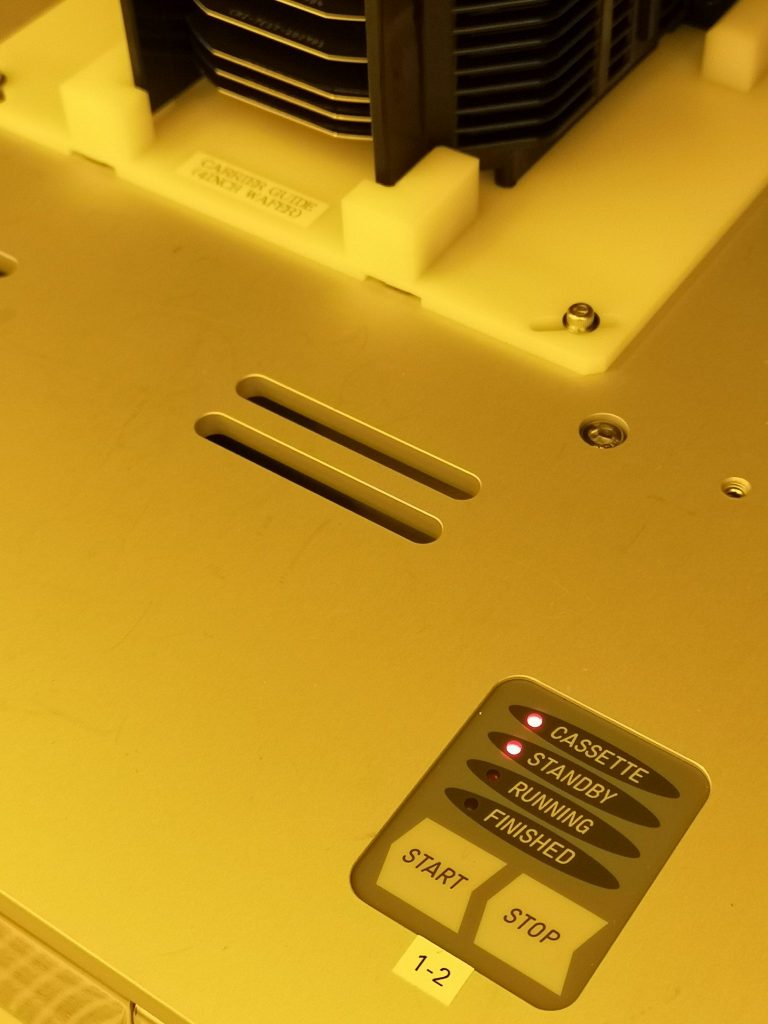
LEDs turns on/off/blinking as follows. Note that FINISHED led blinks during production (do not remove the cassette!).
| LED | Blinking | Steady |
| CASSETTE | Detected | |
| STANDBY | Scanned for processing | |
| RUNNING | Process running | |
| FINISHED | Process running (!) | Process done |
START and STOP buttons can be used to control process, although you may want to choose a recipe first.
b. PRocess Block
PRB is the tool processing core, featuring spinning units (coaters and developers) and thermal plates. Spinning units include:
- Bottom-layer CoaTer (BCT, 2-1) for bottom antireflective coating (BARC) spin from 3 pump lines or 1 Small-volume Dispense System (pressure-driven reservoir, 100 ml capacity). BCT features Reduced-Resist-Consumption (RRC) solvent prewet nozzle, standard Edge Bead Removal needle, and Back Side Rinse nozzle. Due to chemical compatibility issues, this module cannot coat TARCs.
- COaTer (COT, 2-2) for photoresist spin (same characteristics as BCT, but with 4 pump lines).
- DEVeloper (DEV, 2-3) for photoresist development with 2 pressure-driven lines. Dispense is done by type-‘H’ nozzles, featuring 8 parallel streams wetting the rotating wafer during a single, edge-to-center radial scan. Rinse is performed with a high flow DI water nozzle.
Inside spinning units, environmental conditions are tightly controlled: a laminar flow of air at regulated temperature, humidity, and air velocity stabilizes spinning conditions above the wafer; resist/developer temperature is matched to the environment via water-jacketed lines; motor flange temperature is controlled by water circulation to avoid heat transmission via wafer chuck.
Thermal plates come in different types:
- Low-temperature Hot Plate (LHP, 2-13, 2-21, 2-25 2-26, 2-27, 2-28, 2-29,: simple, 1-resistance heating plates for non-critical bakes such as dehydration, post-apply bake (PAB or SB), and hard bake (HB).
- High-temperature Hot Plate (HHP, 2-14): heating plates with extended temperature range for curing/hardening e.g. for BARC bake.
- High-speed Chill Plate (HCP, 2-9, 2-11, 2-12, 2-15, 2-17, 2-19): controlled cooling plates (thermalized water combined with peltier element) for fast cooldown after bakes and temperature stabilization before next process step.
- ADHesion promoter plates (ADH, 2-5): advanced unit for pretreatment using vapor-phase hexamethyldisilazane (HMDS) adhesion promoter.
- Precision Hot Plates (PHP 2-22, 2-23, 2-24): advanced, 8-zones heating plates with precision controllers for Post-Exposure Bake (PEB), featuring an integrated cooling arm to stop baking process independently of machine load and improve wafer-to-wafer consistency. The units come with shaped-flow exhaust and active nitrogen cooling for faster temperature change.
- TRansition Station (TRS, 2-16) and Transition Chill Plate (TCP, 2-15): same as described above, here allowing wafers to pass to the next block (IFB).
Finally, a PRB module holds the Cup WasH disc (CWH, 2-10). At regular time or wafer intervals, this disc with a special backside is brought to COT and BCT units and spun with BSR activated by a dedicated recipe, effectively washing the cup and the splash ring in an automatic maintenance routine.
The Process Robot Arm (PRA, 2-0) transports wafers between modules using up to three pincettes that perform fast wafer exchanges at each module. The attribution of pincettes and the respective wafer clamping method (bottom vacuum or edge mechanical) depend on wafer size.
c. InterFace Block
IFB is the block in charge of connecting the track to the exposure unit. The Interface Robot Arm (IRA, 3-0) shuttles wafers between PRB and the ASML stepper, physically exiting the IFB to reach the input and output ports of the ASML Wafer Transport System. A 25-slot BUFfer (BUF, 3-2) is used to level an eventual difference in speed between the track and the stepper.
Together with the PHPs, IFB is in charge of shot-to-PEB delay control, ensuring stable and reproducible wafer-to-wafer and batch-to-batch results.
d. External modules
Outside the process bay, the following blocks complete the system:
- AC Power Box: supplies electrical power to the system.
- Chemical Cabinet: handles the chemicals to/from the track, including general media (air, nitrogen, deionized water), ADH media (HDMS vapor is generated from liquid reservoir in a skimming tank), DEV developers (2 developer canisters, 10l each), individual COT/BCT solvents (common solvent for EBR and RRC in each module), and individual COT/BCT waste (2 tanks, 20l each). Developer waste has a direct connection to fab drain.
- Cup Temperature and Humidity Controller (T&H): controls the climate inside the tool, allowing to set and maintain temperature and humidity (independent of cleanroom conditions) via a standard dehumidification/humidification/heating sequence.
- Thermostatic water supply (TCU): a rack of combined chillers and peltier controllers for the CHPs, featuring per-plate regulation.
In addition to controlled temperature and humidity, the main unit (CSB, PRB, IFB) is under internal laminar flows with a careful balance of positive pressures, wind speeds, and exhausts to reduce contaminations and ensure the confined environment needed for Chemically-Amplified Resist (CAR) to work properly.
III. Process
The ACT8 track is dedicated to perform DUV lithography using KrF photoresist and ancillary AntiReflective Coatings. The tool is currently equipped with two BARCs and two photoresist as detailed in the following:
| BARC | B1 | DS-K101 | Brewer Science |
| B2 | DUV42P | ||
| Resist | R1 | M108Y | JSR Corporation |
| R2 | M35G | ||
| Developer | D1 | TMA238WA | |
| Solvent | (all) | Microposit EC Solvent | Dupont |
More information can be found here: Photoresist Selection.
Wafers processed in the ACT8 follow the steps detailed in wafer flows. A Wafer Flow Recipe is a recipe consisting of a list of modules, through which each wafer goes sequentially (it is possible to define multiple parallel modules for a given step to increase the throughput). Each step has an associated Process Recipe defining the key parameters for the given step (time, temperature, speed, chemical, etc.). A System Recipe is associated to every flow to set global machine parameters (temperature, humidity, etc.).
Wafer flows are identified by a name after the scheme detailed in the following table:
| Step | Type | Remarks | |
|---|---|---|---|
| Pretreatment | D | Dehydration | For metal or no BARC |
| H | HMDS | For Si, SiO2, Si3N4, etc. | |
| N | (none) | For BARC | |
| BARC | B1 | DS-K101 | Developable BARC |
| B2 | DUV-42P | DRY-etch BARC | |
| __ | (none) | No BARC | |
| Resist | C1 | M108Y | Techno 0.18 μm |
| C2 | M35G | Techno 0.25 μm | |
| – | |||
| Exposure | E | Perform stepper exposure | |
| Post-Exposure Bake | P | Mandatory after E | |
| Development | D | ||
| Hard Bake | H | (resist-specific) | Optional |
| – | |||
| nnn | (numbering) | Application-specific |
The name has always 16 characters, optional parameters are replaced by underscores ( _ ). For example, the standard version of the complete DUV flow with DUV42P/M108Y is named
NB2C1-EPD_-STD
A coat-only flow with HMDS, no BARC, M35G resist, and application “000” gives
H__C2-____-000
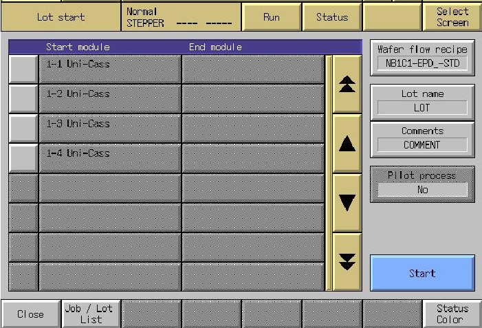
Processing on the ACT8 can be done in Lot or Job mode.
In Lot processing mode, the chosen recipe is executed on the whole casstte(s), regardless the number of wafers and ignoring empty slots. Lot processing is accessible from the home screen following Select screen/Run/Lot start (if the home screen is not accessible, go back to it using Close). Choose the applicable Wafer flow recipe, optionally input a Lot name (start date and time is used if none is provided) and Comments, and start the lot by hitting Start and confirming with OK.
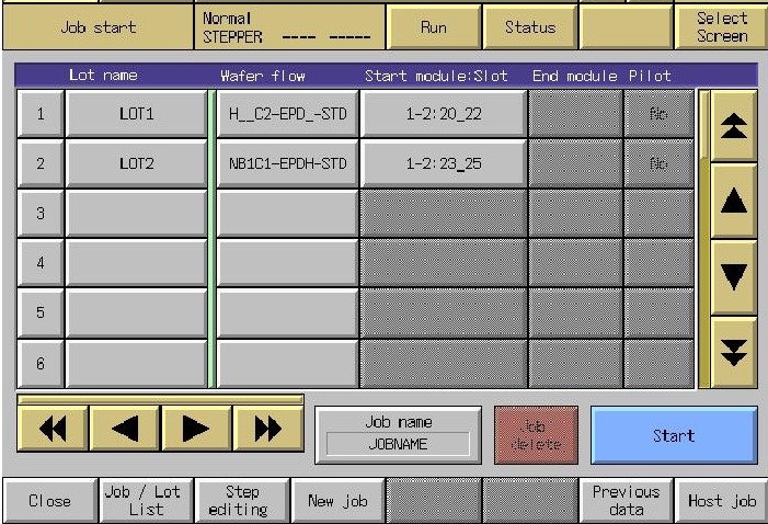
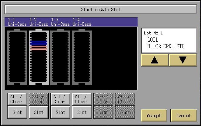
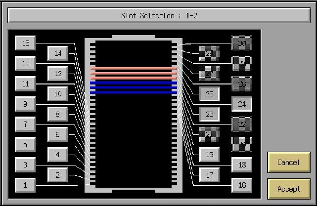
In Job processing mode, one can assign different recipes to each slot of one or two cassettes. Job setup is accessible from the home screen following Select screen/Run/Job start (if the home screen is not accessible, go back to it using Close). Select New Job and optionally input a Job Name (start date and time is used if none is provided) and Comments. Each line of the window can then be filled as a Lot, with an optional Lot Name, and a Wafer flow recipe. When clicking the Start module:Slot field, a graphical selection screen pops up to assign wafers to the current line using the All/Clear and Slot buttons (if more than one lot are preventively set, one can loop through them using the arrow buttons without leaving the wafer selection window). From the Job start window, former jobs can be recalled using the Previous data button and eventually edited using the Modify button. Start the job by hitting Start and confirming with OK.
Ensure the job definition on the track matches the batch stream on the stepper! Tool send each other end control signals that can override the other tool programmed sequence with unwanted results.
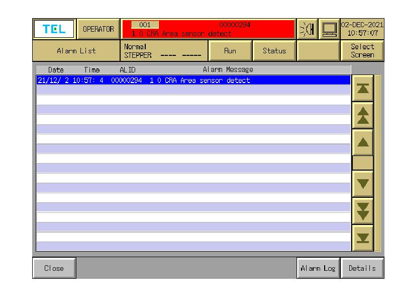
Troubles occurring during production show up in the upper part of the screen. Messages and warnings (non-blocking or blocking at next lot) and Errors (blocking) also trigger the corresponding color in the tower light and the buzzer sound (at simple or double cadence respectively) to draw operator’s attention. A list of common errors and possible actions follows.
|
Lot end |
End of processing for the current lot | If all lots in the cassette are done you can remove the cassette (auto-recovered) |
| Area sensor detect | Loading port light barrier triggered CRA robot pause | Step away from the barrier (auto-recovered). |
|
Time to replace chemical, etc. Stop next wafer Dummy dispense is skipped Empty |
One or more chemicals are running low (there is normally enough material to finish the current batch). | Alert staff immediately (some resist require thawing from -20°C). |
|
Wafer transfer stop |
A wafer spent too much time at a given station. | Check if normal (e.g. long exposure) and if not alert staff (auto-recovered). |
|
Temperature settling Temperature settling timeout |
The concerned plate is adjusting to the new temperature setpoint Adjustment took longer than foreseen |
Wait settling time, all plates except PHPs are quite slow (auto-recovered). If temperature is not changing the heater may be broken (call staff). |
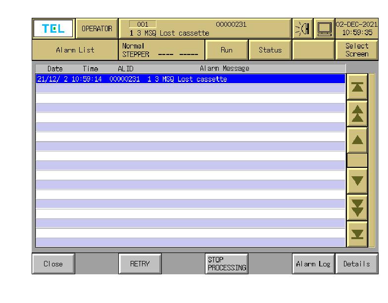
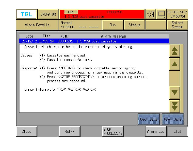
| Lost cassette | Cassette removed before process end | Retry (same cassette!) or Stop processing. |
|
Maintenance Now |
Maintenance ongoing on the tool. | No operation until end of maintenance! |
The following picture shows the aspect of the Warning/Error window and how to get more details if asked by Staff.