Contents
- Introduction
- The ellipsometry in few words
- Equipment description
- How to use the system
- CompleteEase Software and Ressources
I. Introduction ↑
The spectroscopic ellipsometer is used to measure the thicknesses and the refractive indices of thin films (transparent or not).
The ellipsometer allows the study of properties of materials:
- Dielectric and semi-conductor films such as silicon dioxide, silicon nitride, polysilicon and amorphous silicon.
- Metallic films (Note: Generally, the film needs to be really thin)
- Organic layers such as carbon and photosensitive resists.
II. The ellipsometry in few words↑
The spectroscopic ellipsometry is an optical technique using the properties of polarized light, after its interaction with surfaces, to determine refractive indexes and thicknesses of thin films (from a few A to several um depending on material type).
When a linearly polarized light is directed onto the surface of a material with a certain angle of incidence, it can be expressed through its parallel (p-) and perpendicular (s-) components. After reflection on the surface, these components change resulting in an elliptically polarized light.
The ellipsometry uses this phenomenon to give an estimation of the thickness of a transition region between the substrate and the air by measuring the ratio Rp/Rs, the reflection coefficients of s- and p- components. It can be written as :

with Ψ and Δ related to the thickness and the refractive index of the film.
It is important to remind that: the ellipsometer does not directly measure the refractive index (n) or the thickness (t) of the thin film. An algorithm has to be used the resolve n and t based on values of Ψ and Δ measured.

For a given wavelength, Ψ plotted as a function of Δ results in a periodic curve1 for each value of the refractive index (if the material is transparent with k = 0).
The size and position of the curves are optical constants, nature of the substrate, and angle of incidence dependent. Therefore, for a given refractive index, each set Ψ / Δ represents a certain “periodic” thickness. It means that for a given refractive index, the thickness follows its specific and periodic ellipsometric curve.
The measurement in a spectral range cancels the ambiguity related to the use of a single wavelength.
1: For absorbent layers where k ≠ 0, the corresponding graphs are not periodic but have a spiral shape (the corresponding thickness values do not repeat with a constant period)
For more details, do not hesitate to visit Ellipsometry Tutorial from J.A. Woollam company.
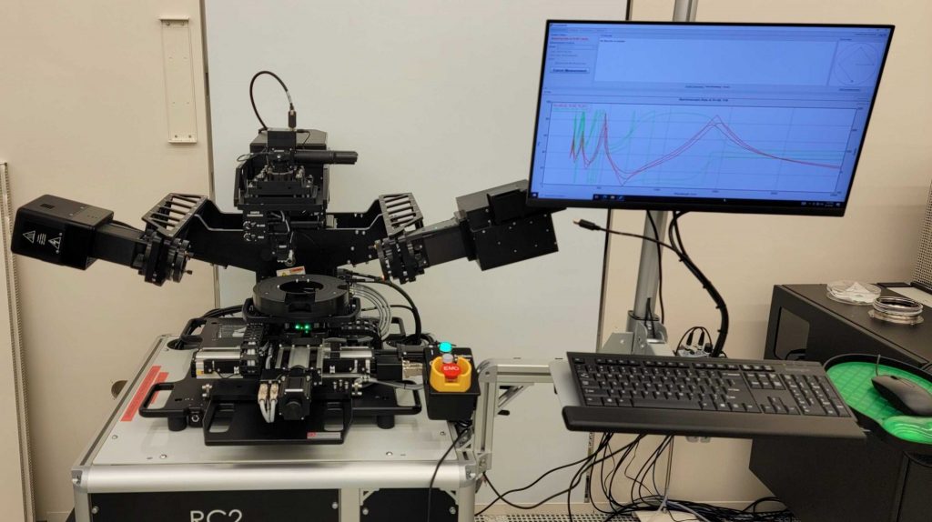
III. Equipment description↑
Substrate size
The system accepts:
- Up to 200 mm wafers
- Chips with a surface for the measurement bigger than the cross section of the incident beam.
Light Source
- Xenon Arc lamp 75W
- Wavelength range : From 210 nm to 2500 nm (UV – Visible light – NIR).
Spot Size
- Without focusing probes : 3 to 4 mm beam diameter
- With focusing probes : 120 microns beam diameter
Table X-Y-Z
- Motorized XY stage mapping
- Motorized Z and Autofocus
- Automatic Tilt Alignement
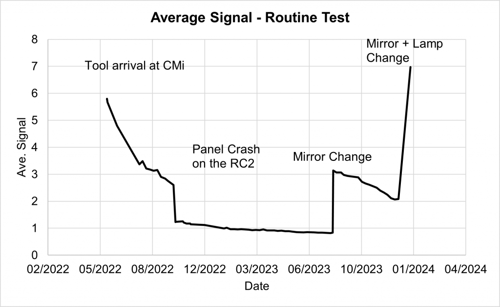
Routine Tests – Evolution of the light signal intensity
IV. How to use the system↑
V. CompleteEase Software and Ressources↑
CompleteEase
- The software manual can be consulted on the tool directly by clicking on F1 or in the Options tab.
- Short video tutorials can be found on J.A. Woollam website.
- CompleteEASE Course Online Training given by Quantum Design GmbH.
Ressources
- James N. Hilfiker, Neha Singh, Tom Tiwald, Diana Convey, Steven M. Smith, Jeffrey H. Baker, Harland G. Tompkins, Survey of methods to characterize thin absorbing films with Spectroscopic Ellipsometry, Thin Solid Films, Volume 516, Issue 22, 2008, Pages 7979-7989, ISSN 0040-6090, https://doi.org/10.1016/j.tsf.2008.04.060.
- James N. Hilfiker, Greg K. Pribil, Ron Synowicki, Andrew C. Martin, Jeffrey S. Hale, Spectroscopic ellipsometry characterization of multilayer optical coatings, Surface and Coatings Technology, Volume 357, 2019, Pages 114-121, ISSN 0257-8972, https://doi.org/10.1016/j.surfcoat.2018.10.003.
- Tompkins, Harland G., and James N. Hilfiker. Spectroscopic Ellipsometry : : Practical Application to Thin Film Characterization. Momentum Press, 2016.
- Synowicki, R.A. (2008), Suppression of backside reflections from transparent substrates. Phys. Status Solidi (c), 5: 1085-1088. https://doi.org/10.1002/pssc.200777873