To be read first:
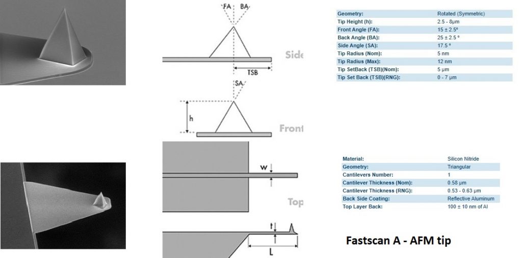
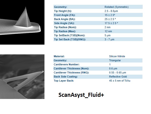
- Each user/lab has to have at least one box of CMI compatible tips (ScanAsyst Fluid+, Fastscan A or Fastscan C).
- Each user has to know how to replace a AFM tip.
- Each user has to leave the AFM with a fonctional AFM tip in place among the 3 references below. (ScanAsyst Fluid+, Fastscan A or Fastscan C).
NEW VERSION (08.05.2025) : User manual
RESERVATIONS RULES AND BILLING POLICY :
- Booking : No restriction
- Reservtion names must be correspond to operators
- Billing : Processing time
- No penalty fees in case of user’s no show
CONTENTS :
II. AFM_technique – short description
III. Tip_change
IV. How to start a measurement
VI. Data acquisition (Nanoscope V9.3)
VII. AFM_Data_Treatment (Nanoscope analysis)
VIII. Links
IX. Gallery
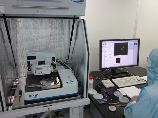
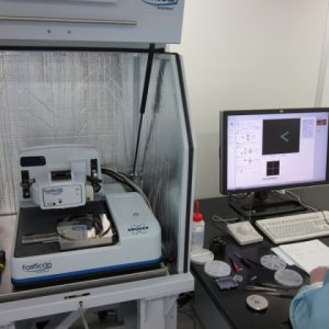
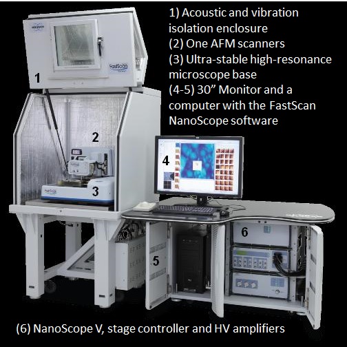
I. Equipement description
Tool – general information
The chuck is compatible with 2”, 3”, 4”, 6” and 8” wafers with a thickness lower than 15 mm. The chuck is also compatible with dies with a thickness lower than 7.5 mm. The chuck is motorized for an inspection area of 150×180 mm. The chuck can be manually rotated. The unidirectional stage repeatability (X&Y) is 2.0 um and 3.0 um for the bidirectional repeatability.
The tool is equipped with a digital camera (5MP), the viewing area ranges from 130 um to 1465 um for the FastScan scanner.
The Fastscan scanner – Technical data
At CMi, the FastScan AFM scanner is compatible with the modes ScanAsyst, TappingMode (air) and Contact Mode.
The main scanning parameters are :
- X-Y scan range : 35um x 35um maximum
- Z range > 3um,
- Vertical noise floo < 40pm RMS, sensor in appropriate environment (up to 625kHz)
- X-Y position noise (closed loop) < 0.20nm RMS typical imaging BW
(up to 2.5kHz in Adaptive) - Z sensor noise level : 30pm RMS typical imaging BW (up to 625Hz)
- X-Y flatness < 3nm (30um range),
- Integral nonlinearity < 0.50% (X-Y-Z)
II. AFM technique – short description
Atomic force microscopy (AFM) is a very-high-resolution type of scanning probe microscopy (SPM), with a resolution on the order of Angstroem (A). The high resolution in XY and Z is ensured by the coupling of piezoelectic elements with the probe on the end of the cantilever.
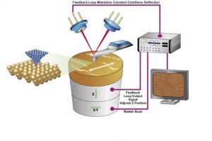
The tapping mode is the most common mode nowdays for scanning in air. The cantilever is driven to oscillate up and down at or near its resonance frequency. The frequency and amplitude of the driving signal are kept constant, leading to a constant amplitude of the cantilever oscillation as long as there is no drift or interaction with the surface. The interaction of forces acting on the cantilever when the tip comes close to the surface, Van der Waals forces, dipole-dipole interactions, electrostatic forces, etc. cause the amplitude of the cantilever’s oscillation to change (usually decrease) as the tip gets closer to the sample. This amplitude is used to adjust the height to maintain a set cantilever oscillation amplitude as the cantilever is scanned over the sample. A tapping AFM image is therefore produced by imaging the force of the intermittent contacts of the tip with the sample surface
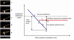
At CMi, we used to use an evolution of the historical tapping, named Peak Force Tapping. In PeakForce Tapping mode, the probe periodically taps the sample and the pN-level interaction force is measured directly by the deflection of the cantilever. More information and a detailed description are available in the documents Introduction To Brukers ScanAsyst And PeakForce Tapping and PeakForce Tapping.
III. Tip change
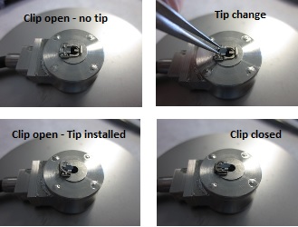
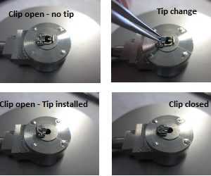
The step by step procedure below describes how to change the tip. The procedure is illustrated by the photos gallery above.
- Login on the zone computer.
- Double-click on Nanoscope V9.3 icon to start the application.
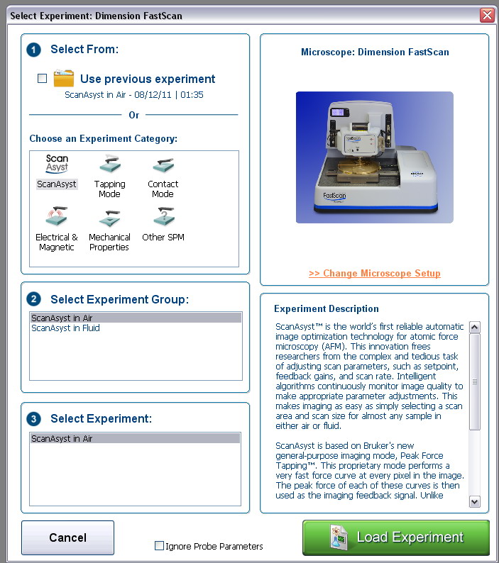
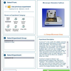
- Select an experiment from the Experiment Category (e.g. ScanAsyst) and click on Load Experiment.
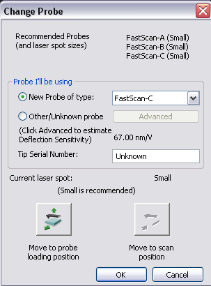
- In the main menu of each scanning mode (or experiement), select Setup then Change probe and then click on Move to probe loading position. The chuck moves outside from the scanning head area.
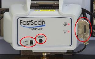
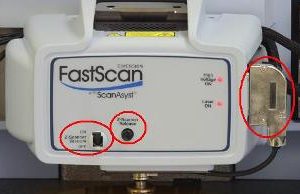
- Switch off the vacuum on the fastscan head, press 2 or 3 times on Z-scanner release to break the vacuum between the Z-piezo and the XY head.
- Unplug the connector of the piezo and take the Z-piezo with 2 fingers on the sides to detach it.
- Put it face up on the dedicated support.
- Unclip the fork with a metallic tweezers and move it at the opposite side.
- Remove the tip from its support and stick it in one box.
- Select a new tip and place it in the metallic slot. The back of the tip has to be in contact with the metallic edge of the Z-piezo.
- Move back the fork and clip it.
- Take the piezo Z with 2 fingers and attach it on the XY head.
- Switch on the vacuum and plug the electrical connector.
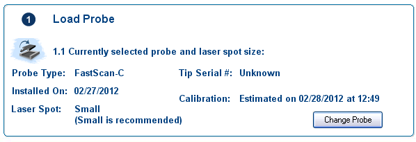
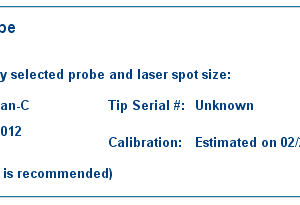
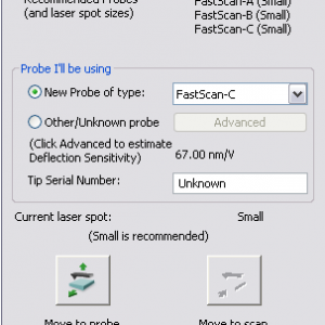
- Select the name of the probe in the library.
- Adjust manually the laser spot size according to the specification.
- Press Save and return, the chuck goes back to its previous position.
- Select the menu Setup to finalize the settings of the laser.
IV. How to start a measurement

The step by step procedure below describes how to do a measurement once your are login on the zone computer. The procedure is illustrated by the photos gallery above.
The data acquisition is done with the software Nanoscope V9.3. Double click to open it and select an experiment (or scanning mode) from the Experiment Category (e.g. ScanAsyst) and press Load Experiment.
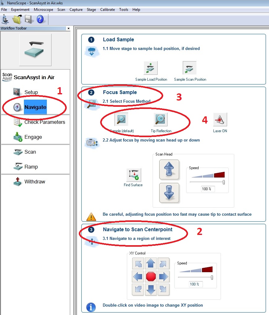
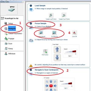
On the left of the window, you see the 5 menus that we need to carry out AFM measurements :
- Setup : to set the AFM parameters.
- Navigate : to position your sample and move the AFM tip close to the surface of your sample.
- Check parameters : to control the scanning parameters used by the system to start the measurement.
- Engage : to start the automatic scanning of your sample.
- Withdraw : to stop the scanning of your sample.
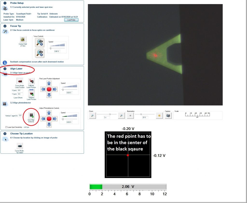
What to do / to check in the menu Setup:
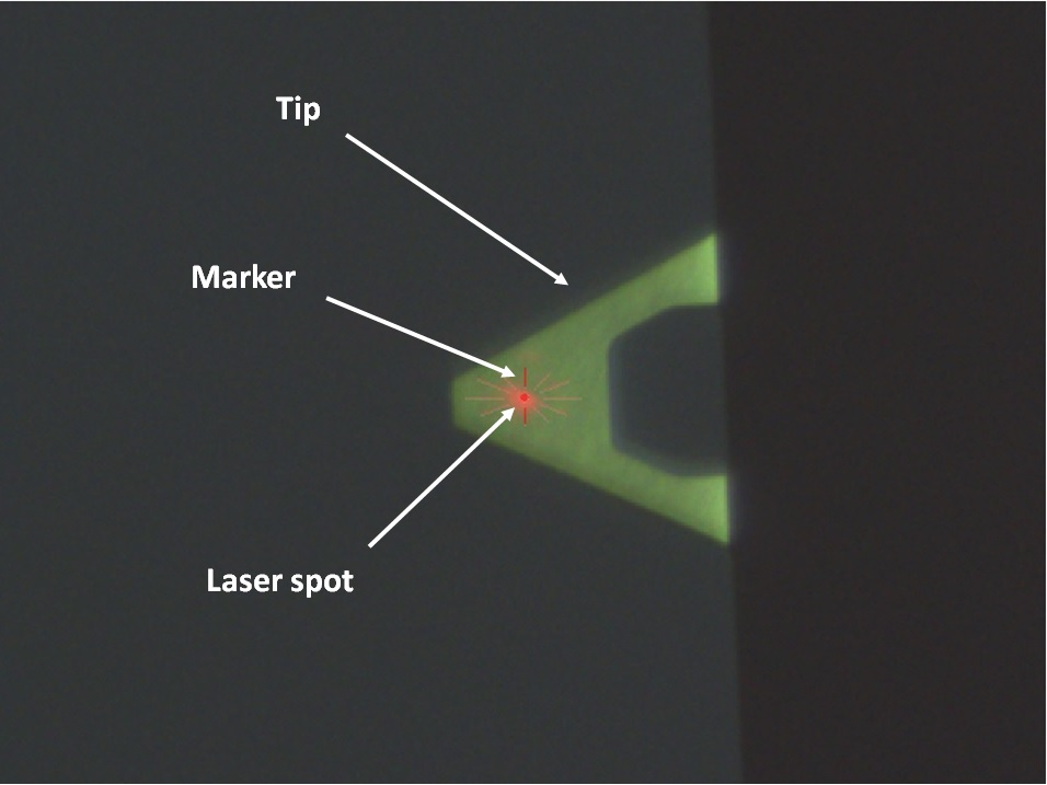
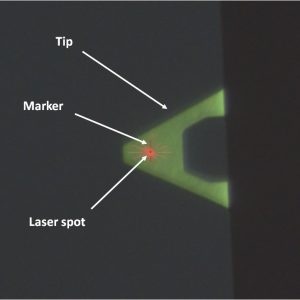
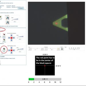
- On the CCD camera window, you should see 3 elements :
- the tip
- the red marker (red star)
- eventually the laser itself (depend on the installed tip)
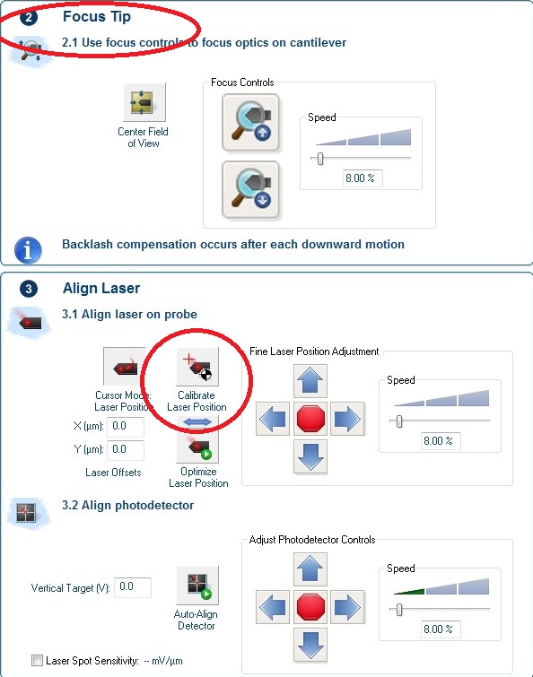
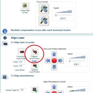
- The tip : You can improve the focus by click UP or DOWN with the corresponding arrows in the sub menu Focus Tip (2).
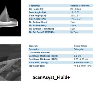
- The marker and the laser have to be aligned because the laser is not always visible on the tip contrary to the marker. Then you can easily move the marker. To do it, (if you see the laser and only if you see the laser) activate the routine Calibrate Laser Position in the sub menu Align Laser (3) (a large red cross appears) and click on the laser and press Save and Return. If you don’t see the laser, click on the edges of the tip to see it. The correct final position of the laser/marker is close to the end of the triangular shape of the tip for ScanAsyst Fluid+ tips.
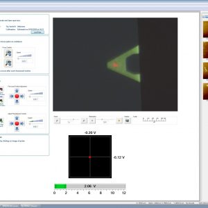
- The next step is the alignment of the laser’s reflection on the tip on the photo diodes. The actuel position of the laser is represented by the red point in the square made of 4 black blocks. To be aligned, the red point (laser reflection) has to be in the center of the square. The alignment is done automatically by the system by activating the routine AutoAlign Detector. The intensity of the green bar has to be higher than 1.0V at the end of the aligment.
- If nedded it, you can also indicate roughly the position of the AFM probe to the system by activating the routine Choose Tip Location (4). A blue cross appears. You click on the tip where you think the AFM probe is (Top view). You have an SEM view of the ScanAsyst Fluid + in the gallery to give you an idea where is physically the probe. The accuracy is not more 3 – 4 um.
You can now install your sample on the chuck, switch on the vacuum (if relevant) and click on the menu Navigate .
What to do / to check in the menu Navigate:
- With the arrows of the sub menu Navigate to Scan Centerpoint (3), move your sample below the XY head.
- Then move down the XY head with the arrows in the sub menu Focus Sample. At the beginning, a direct visual control is enough until you are close to the surface (3 mm) then you have to switch on the window of the CCD camera.
- At this stage, you have 2 options: either you have patterns scratches/dust or significant topography, in this case you can continue with the default mode until you see something on the surface or your sample is very clean or transparant you have a lot of chances to scratch the tip on the sample and damage the Z-scanner. In this case, you have to select and continue the move down the Z-scanner with the mode Tip Reflection until you see the shape of the AFM tip.
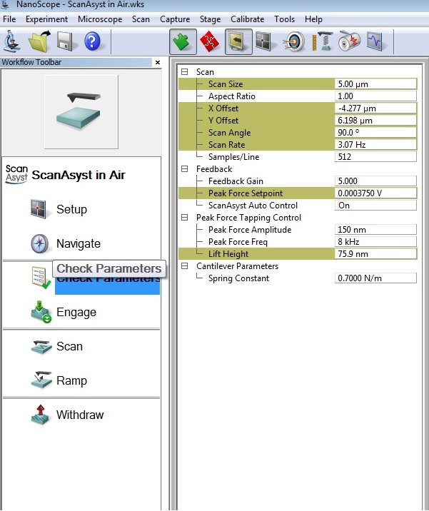
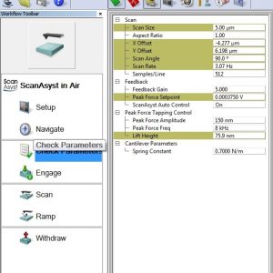
Now you are almost ready to start the measurement. You just need to click on the menu Check Parameters. The list of the scan parameters by default appears, please check that the ScanAsyst Autocontrol Mode is ON to let the system tune the scanning parameters itself. Once the measure is stabilized, you have the opportunity to modify the scanning parameters as you wish (see Data acquisition).
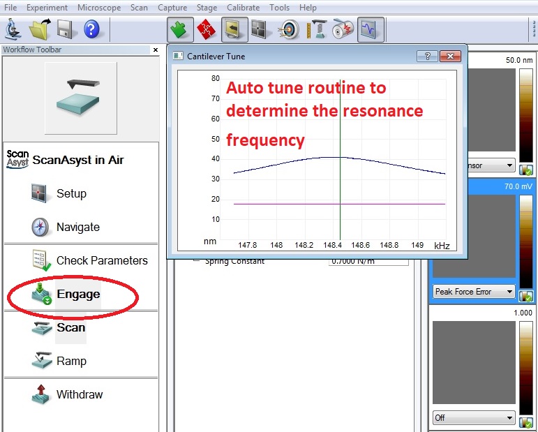
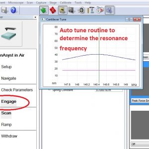
By clicking on the menu Engage, you start the fully automatic routine consisting of the determination of the resonace frequency of the tip and the final appraoch of the tip very close to the surface of your sample at the measurement distance before starting the automatic scanning.
Once the scanning of the samples is done and the data saved, you stop the measurement by click on Withdraw. The XY head moves up. To take back you sample, you have to go back in the menu Navigate and click on Move Sample to Load Position or you go back to the menu Setup and click on Move to Probe Loading Position.
V . Small samples
The chuck is compatible with 2”, 3”, 4”, 6” and 8” wafers but can also scan dies or pieces of sample. In the last cases, you can not use the vacuum of the system to perfectly stick the sample on the AFM chuck. To avoid parasitic oscillations during the measurement, it’s strongly recommanded to stick the sample on an intermediate support compatible with the AFM chuck.
You have 2 options:
1. You stick the sample on a 4 ” wafer and use the AFM vacuum to stick the wafer on the AFM chuck
2. You stick the sample on a stainless steel piece then you put the stack on a dedicated magnetic support which is stuck itself on the AFM chuck.
For the sticking, you can either use small circular kapton pieces or double face stickers.
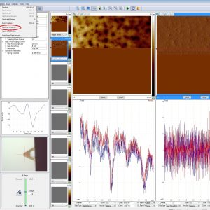
VI. Data acquisition (Nanoscope V9.3)
During the acquisition, you have access to the following basic scanning parameters:
- Scan Size : The maximum scan size is 35 um x 35 um. It’s recommanded to start with a limited size 1 x 1 um before making it larger step by step if necessary. To save time you can also modify the aspect ratio from 1:1 to 1:2 or 1:4.
- XY Offset : This function can be useful for limited displacement to center your image without moving the chuck. You have the same functionality at the bottom of the scanning window. Click on Offset to activite it, click on the futur center point of your scan and then press activate. The scannng window will move in consequence.
- Scan Angle : we can enter a scan angle in any direction (0° corresponds to an horizontal scan of the screen). With an AFM, it ‘s recommended to scan perpendicularly to the step.
- Scan Rate : The scan rate determine the acquisition time. The standard value in the ScanAsyst mode is 3.76 Hz with AFM tips provide by CMi. But depending on the topography of the sample, it can be much lower around 0.5 Hz. A too fast scan rate can induce a definitiv damage of the AFM tip.
- Sample/Line : This is the number of points you have for each scan (trace en retrace). higher the number, more accurate the results, but longer the acquisition time. The standard value is 512, but to save time during the localisation of the scanning area, you can decrease it at 128.
You have also access to the following basic feedback parameters:
- Feedback gain : This parameter corresponds to the force that is apply to the cantilever during the oscillation of the tip. You can control it if you switch OFF the ScanAyst Auto Control.
- Peak Force Setpoint : This parameter corresponds to the reactivity of cantilever in contact with a step. You can control it if you switch OFF the ScanAyst Auto Control.
- ScanAyst Auto Control : During scanning on large area, you can face to instability issue. It can be somtimes useful to frozen the scanning parameters of Z-piezo. You can do it by switching OFF the ScanAyst Auto Control.
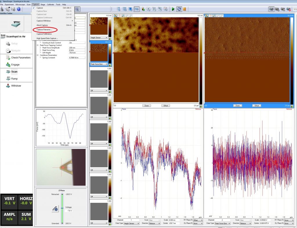
At the end of a scanning from top to bottom or reverse, you can save the date with the fonction Capture (top right of the scanning window).
You can also save a part of the scanning by click on Save Now (top right of the scanning window).
You can also save multiscans of the same area by click on Save Continous (top right of the scanning window).
All files with the rough data are saved in your directory on :
sti1files\cmi-transfer\Z15_AFM\YourLab\YourName
VII. Data treatment (Nanoscope Analysis)
The data treatment is done with the software Nanoscope Analysis. This software is a free software avaialable in the directory :
sti1files\cmi-transfer\Z15_AFM\Nanoscope Analysis
The software has a very exhaustive list of functionalities among them: Flatten, roughness, localize roughness, cross section, 3D etc ….
You can find more information on the functionalities in general and more details on each functionality in the help of the software or in the document NanoScopeAnalysisV150Manual.
VIII. Links
- Introduction To Brukers ScanAsyst And PeakForce Tapping
- PeakForce Tapping
- NanoScopeAnalysisV150Manual
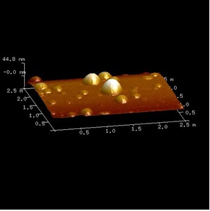
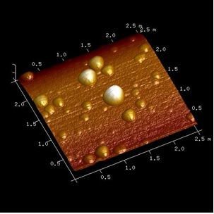
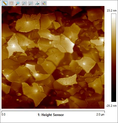
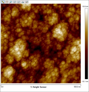
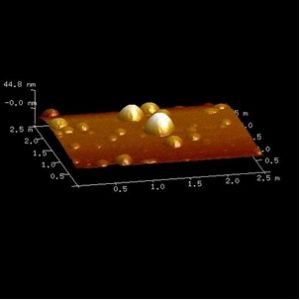
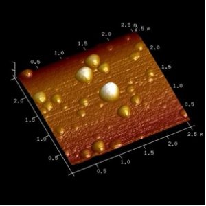
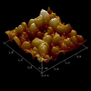
IX. Gallery