- This equipment handle only Standard Cr-plate or SEMI wafer from cassette
- Double-check that all window bays are closed when leaving the tool!
- SU8 thicker than 50µm without manual edge bead removal will contaminate nozzle and internal optics
- Exposure of AZ10XT at any thickness are forbidden to avoid resist particles projection directly on the front lens. (use MLA150 @ 405nm)
- Overlay exposure with top side alignment require precise wafer flat pre-alignment with a maximum tolerance of ± 10 mrad.
- The equipment is sensitive to airborne solvent contamination on optical elements, and is equipped with charcoal filters. Always double-check that the window bay is closed when leaving the tool!
- When fabricating projection reticles for the ASML stepper special rules apply. Do not hover on top of a reticle with hands or body. Use a mechanical pick (available in Z5) whenever possible, or at least chemistry double gloves. Except at load/unload operations, handling and all types of inspection are forbidden on production reticles. Reticles handled for showing, optical microscope check, SEM inspection, and everything else but entering/exiting reticle pods must be considered unusable for production and thus scrapped. For in-house reticle fabrication, users can optimize writing parameters (energy, focus, design bias, etc.) on a 5″ soda lime mask (film stack and resist are identical) that is easy to inspect and then blindly repeat on 6″ quartz plates on the same day.
RESERVATION RULES AND BOOKING FEES POLICY:
- Booking: maximum 10 time slots allowed at any time.
- Reservation names must correspond to operators.
- Billing : 6 minutes + processing time.
- This equipment is subject to penatly fees in case of user’s no-show.
Contents:
I. Introduction
The VPG200 (Volume Pattern Generator) is a laser pattern generator developed by Heidelberg Instruments GmbH in Germany. This system allows researchers to produce masks for use with maskaligner, direct exposure of resist on SEMI-standard wafers or mask reticules for the DUV stepper. Illumination of resist with a UV laser (355 nm) beam focused over the substrate is optimized for very high speed dense pattern. Image reconstruction is performed by projection of two linear arrays of 1000 pixels combined with mechanical movement of the stage. Easy interchangeable lenses offer different specification for writing speed and magnification.
High throughput capability with batch mode substrate handling from standard cassette.
Camera installed behind the same projection optics can be used to align to perform overlay exposure on an existing pattern (top side alignment only).
VPG 200 support CAD-generated layout of standard file formats (.gds, .cif, .dxf,…). Himt convert interface are similar for both Heidelberg laser writer installed in the CMi clean room.
The resolution is limited by the photoresist, wavelength and resolving power of the optics (NA, depth of focus), and can reach a minimum of about 600 nm with thin photoresist (PR) thickness (< 1 µm).
II. Equipment description
VPG200 devices and tools:
The VPG200 user interface offer different user level with increasing complexity. Basic level is very intuitive.
Basic level:
Use wizardry like script editor which require only two parameters:
- Laser Intensity (% of maximum available laser power):
Controls the exposure dose. The dose is calibrated for standard mask sensitivity. Conversion factor to exposure dose are available for each optics. Keep in mind that the light source and exposure conditions are not the same as with a mask aligner so optimal dose and exposure results will be slightly different. - Defocus: defines where the focus is done. If set to zero, focus is done at the top of the resist, a positive defocus will shift the focus downwards inside the resist
Advanced level:
This mode give individual access to the main components (handler, pre-alignment, cameras, XY stage control, jobs and alignment script editors) commonly used for more complex tasks. Teaching this mode require an additional training session (i.e., for overlay exposure )
Equipment configuration:
The VPG200 system is equipped with:
- Off-line setup and conversion of CAD-files on the linux workstation (free of access)
- Exposure source: 355 nm wavelength, pulsed Q-switched DPSS laser
- 2 cameras: macro and micro for manual or automatic detection of alignment markers (top side only)
- Real time autofocus
- Stage system, position control with interferometers, chuck with vacuum for various substrate sizes
- Masks and reticules (4, 5, 6, 7 inch) and wafer (100 and 150mm SEMI-standard ) cassette station
- 3 interchangeable optics: Write Head 4, 10, 20 mm focal length
Equipment specifications:
The VPG200 system offers the following specifications:
Values are for basic mode and 4, 10, 20 mm write Head respectively
- Critical Dimension: 0.6, 0.9 and 2.0 μm
- Minimum feature size: 500nm
- Pattern edge roughness: XY direction dependent. max 90, 140 and 250 nm
- Alignment accuracy: <300, 400, 800 nm
- Maximum substrate size: 7″x7″sq or 200 mm diameter
- Maximum exposure area: 7″x7″ sq.
- Designs compatibility: cif, gdsii, dxf , gerber
- Writing time with handling (5″x5″ sq. 110×110 mm): 7, 18, 65 min.
- Batch processing up to 20 5″ masks or 25 wafers
- Single exposure or multi-design/parameters mapping
III. User manuals
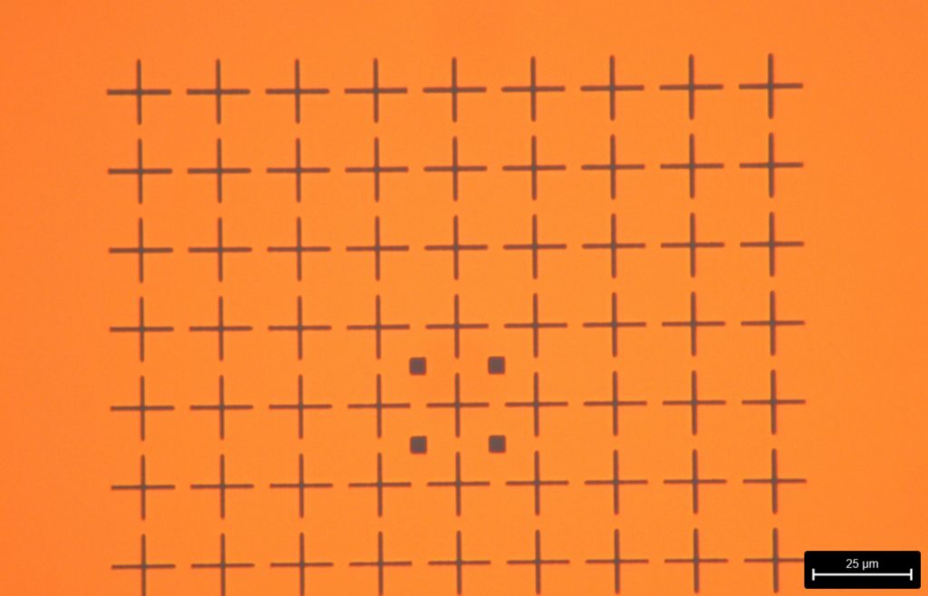
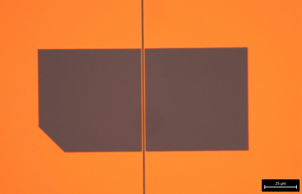
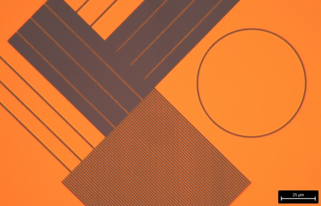
IV. Pictures gallery