To avoid delamination and flakes generation, the evaporation of Si/MgF2/SiO2/Al2O3 and more generally oxides is allowed only the week before the monthly cleaning of the chamber (Subject to exceptions – Please ask CMi staff).
Contents
- Introduction
- Equipement description
- Standard recipes
- How to use the system
- Restrictions and precautions
- References
I. Introduction ↑
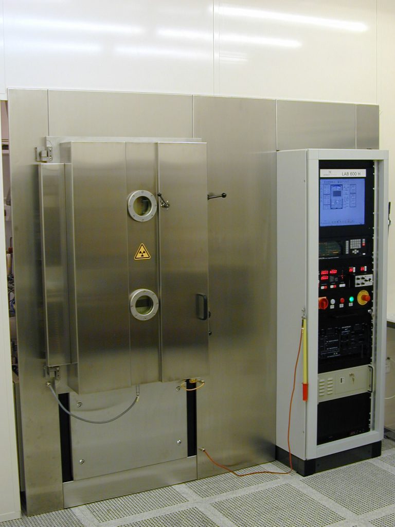
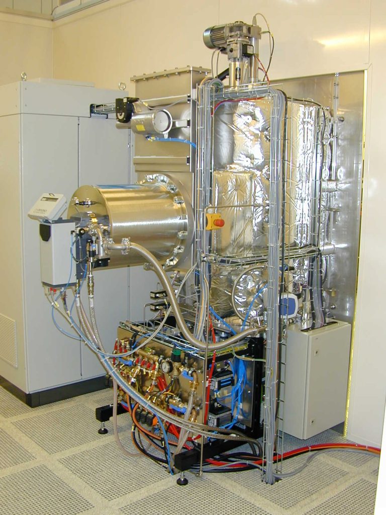
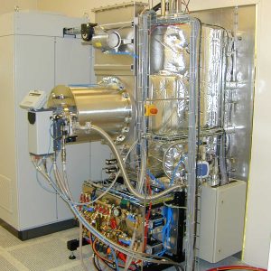
The LAB 600 H is an equipment allowing the deposition of metallic or dielectric layers on 100 mm or 150 mm wafers by evaporation.
This method involves evaporating a material placed either in a crucible heated up by an electron beam or a boat heated up by Joule effect.
The LAB 600 H is especially designed for:
- Lift-Off processes requiring a material deposition closed to the normal of the sample.
- The deposition of dense dielectric films requiring ionic source assistance.
II . Equipement description ↑
Dimensions and capabilities
The maximum working distance (distance source – substrate) in the LAB 600H is 1010 mm. Such distance allows to minimize the angle between the normal on the edge of a wafer and the incident flux of evaporated material.
Volume of the chamber : ~ 640 l.
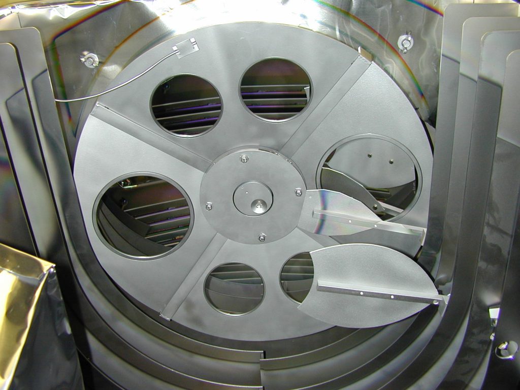
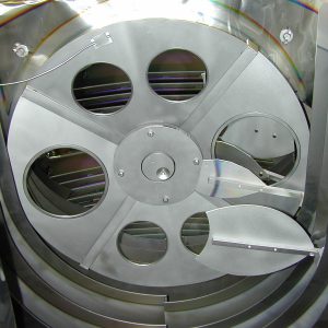
The substate holder is composed of 4 segments. Each segment can receive 2 x 100 mm wafers or 1 x 150 mm wafer.
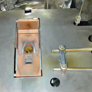
Evaporation systems
Historically, LAB 600 H was equipped with:
- Electron gun evaporation: Ferrotec EV M-8 ; 10 kW , 6 pockets
- Joule-Effect evaporation : 1 boat ( maximum currect : 400A) – Remark: This system has been removed from the chamber.
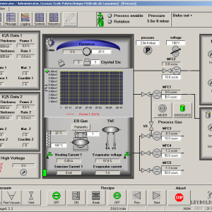
Film thickness measurement
The film thickness is determined by following the change in frequency of a quartz crystal. This change is due to the growing mass of material on top of its surface. Thanks to some calibrations, the variation can be related to the thickness of the film deposited.
- Deposition controller : Inficon IC/5.
- 1 x carousel with 6 quartz crystals QSK 621 at the center of the substrate holder.
- 2 x Quartz crystals on the side of the chamber.
Pumping
To reach high vacuum, the system is equipped with a cryogenic pump.
- Primary dry pump Ecodry L (Leybold) – Pumping speed = 40 m3h-1 ;
- Roots pump Ruvac WSU 501 (Leybold) – Pumping speed max. = 500 m3h-1.
- Cryogenic pump Cryopump CTI OnBoard 400.
- Pumping capabilities:
- N2 = 6000 l/s
- H2O = 17 500 l/s
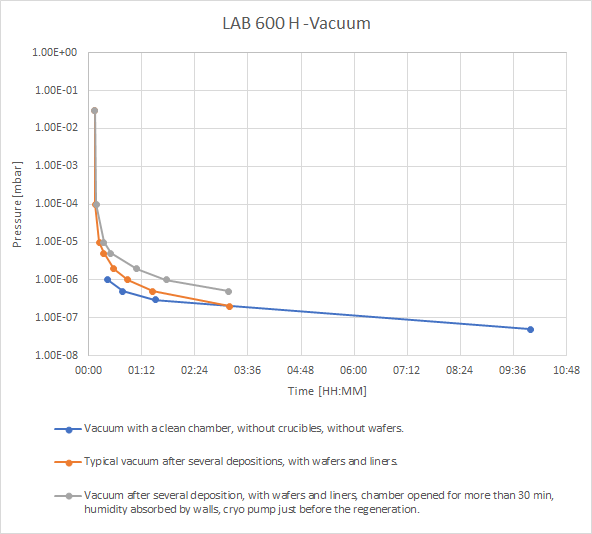
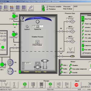
Pressure
The pressure in the system is measured by:
- 2 x Gauges Pirani PSG 100-SP : Primary vacuum control (10+3 à 10-3 mbar).
- 1 x Gauge Bayard-Alpert BAG 100-SP : Secondary vacuum control (10-1 à 2.10-10 mbar).
Typical vacuum levels are:
- ~ 1.5 10-6 mbar in normal use conditions.
- 1.0 10-7 mbar with a clean chamber and after 8h under vacuum.
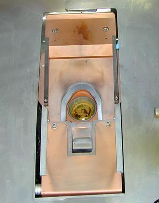
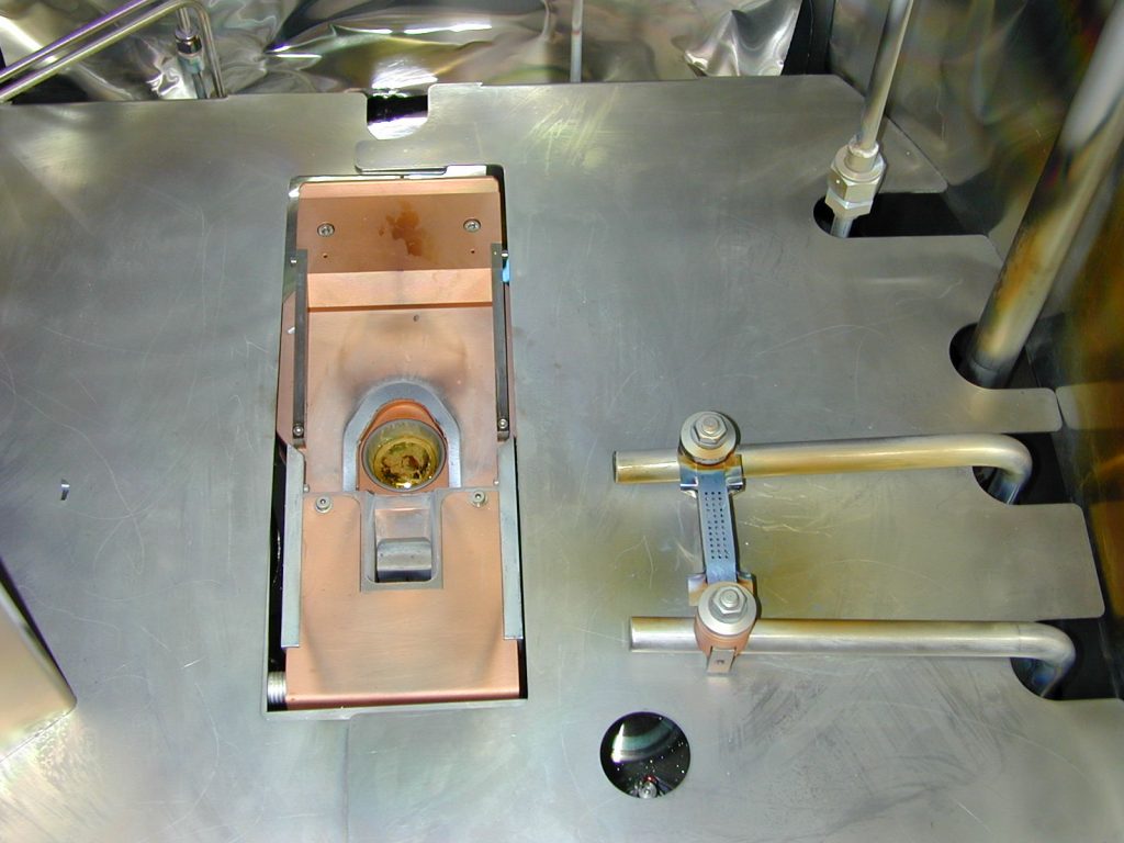
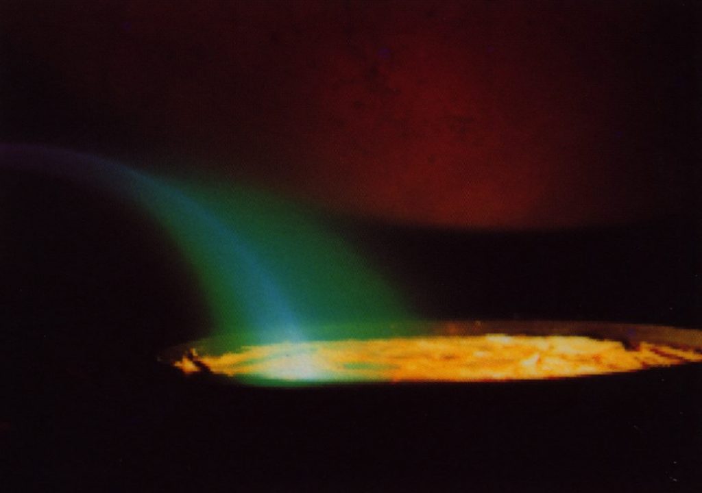
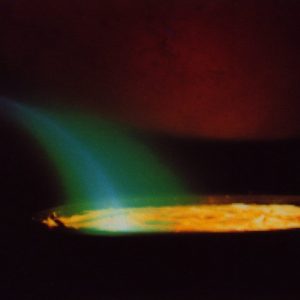
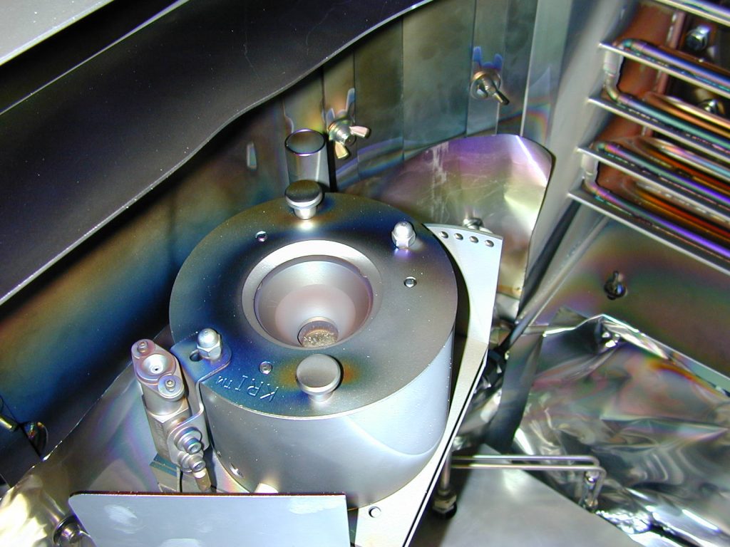
Ion Source
The ion source used to densify the dielectric films is Kaufmann & Robinson type, Inc. KRI ™ EH1000 (End-Hall Ion Source). It is equipped with a hollow cathode electron source KRI SHC-1000. The ion bombardment during the deposition improves the film properties in terms of density, hardness, refractive index, better resistance to the environment and better control of internal stress.
The ion source can also be used to clean wafers before the deposition:
- The contamination targeted is the water vapor absorbed by surface and the hydrocarbon coming from the environment (Ion dose = ~1 mA.s.cm-2 enough to get ride of it). Both can reduce the adhesion of the film on the surface of the sample.
- The native oxide can be also targeted but the ion dose has to be much more important.
The efficiency of the ion source depends on the ion flow and the energy of these ions.
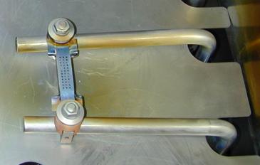
The KRI SHC-1000 electron source is used to neutralize positive charges appearing on the substrates during ion bombardment.
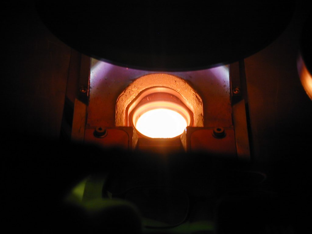
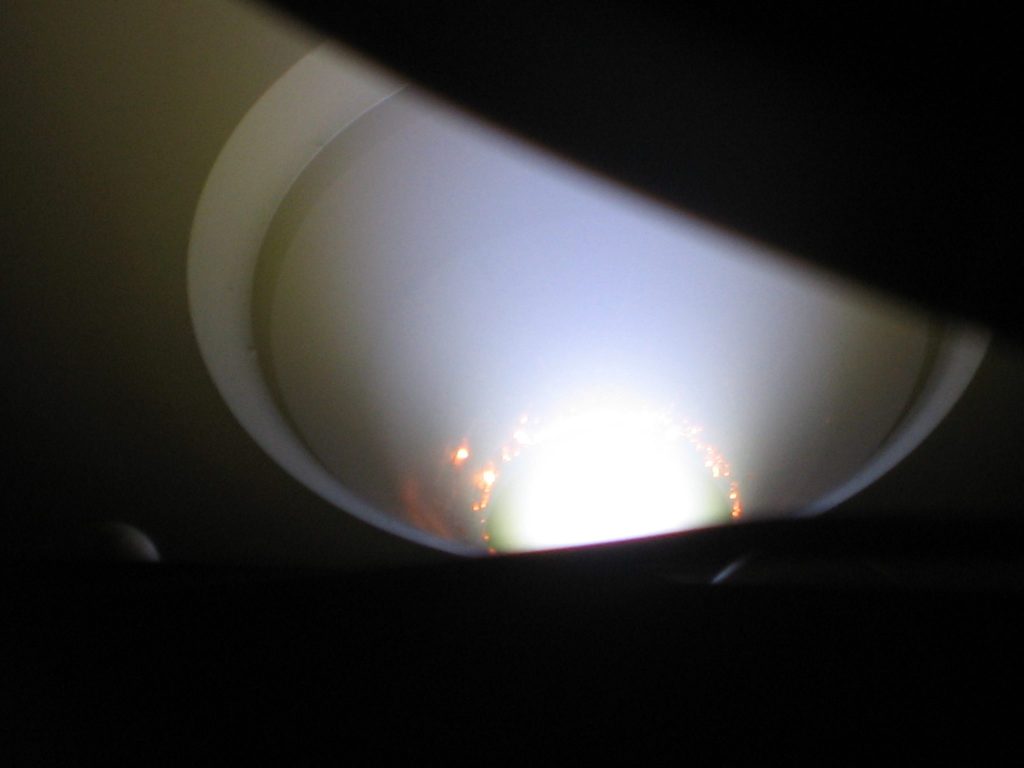
Argon is first introduced into the hollow cathode. Plasma discharge is obtained by applying a high voltage between the end of the hollow cathode and the keeper. The plasma ignition leads to VK voltage reduction, the increase of IK current and the increase of the temperature of the hallow cathode until the stabilization of the system. The lowest VK voltage reached allows maintaining the plasma.
As soon as the hallow cathode is operational, the Bias controller – Neutralizer applies a voltage to start electrons emission for positive charges neutralization.
The maximum value for IK current is 10 A. The Ar flow recommended is 10 sccm.
Some electrons are deflected towards the anode of the ion source (without reaching it due to the presence of a magnetic field generated by magnets of the ion source). The interactions electrons / working gas (Ar, O2) give ions. Most of the ions are generated inside the anode, then they are accelerated thanks to an electric field toward the surface of samples.
The discharge current (Discharge controller) can reach 8 A and the maximum discharge voltage is 300 V. To not damage magnets, the maximum power tolerated is 850 W.
Here is the max. discharge voltage VD as a function of discharge current ID:
| ID | VD max. |
| 1.8 A | 300 V |
| 2.8 A | 300 V |
| 3.4 A | 250 V |
| 4.3 A | 200 V |
| 5.7 A | 150 V |
| 7.1 A | 120 V |
| 7.5 A | 113 V |
The pumping speed depends on the capability of the cryogenic pump but also the configuration of the tool (i.e Distance flowmeters – pump). If the pumping speed is too slow, the desired VD max. for a fixed ID can be reached.
The pumping speed can be estimated with the formula : v = 9,225.10-3 . Ø / p : with v the pumping speed [l/s], Ø the gas flow [sccm] and p the pressure in the chamber [mbar].
For slow pumping speed (i.e 600 – 800 l/s), the discharge current VD is limited to 80 – 125 V (with ID = 1 A). For fast pumping speed (i.e > 1100 l/s), VD reaches its maximum : 300 V (with ID = 1 A).
In the LAB 600 H is estimated between 1200 l/s (ØAr = 10 sccm) and 1340 l/s (ØAr = 100sccm). It means that the ion source installed in the system can be used at 100% of its performance.
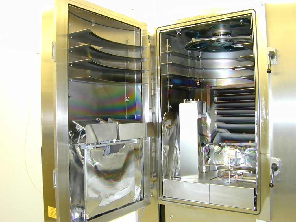
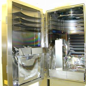
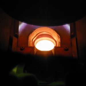
Heating
Two heaters placed on the door can be used to heat up samples.
- 2 x ceramic radiants ( 1,8 kW each)
- Deposition temperature max. = 190°C
III. Standard recipes ↑
Only thicknesses (for each layer) can be changed. For recipe creation, please contact responsibles of the tool.
For details concerning precious material billing, see Processing fees page.
IV. How to use the system ↑
All the actions to operate the system are detailed in the user manual.
V. Restrictions & Precautions ↑
- Allowed substrates are Silicon, Sapphire, Glass (Quartz, Pyrex, Float). For any other substrates please confirm with CMi staff.
- For all processes at high temperature, two consecutive slots are required to complete the process properly. Please adjust your reservations accordingly.
- To obtain a reproducibility of the refractive index obtained for transparents films, it is necessary to use the heater & the ion source and to work with a clean chamber. Actually, the ion bombardment used to densify films causes the heating up and the sputtering of the surfaces closed to the source. The sputtered elements may contaminate the film during the evaporation.
VI. References ↑
- “FerroTec – EV M-8 Operation Manual”
- “EH1000 Ion Source Manual HCES version”, Kaufmann & Robinson Inc.