The CMI’s SEM MERLIN is exclusively reserved for imaging dedicated to the control of processes which have been done in the CMI by the regular CMI users.
RESERVATION POLICY:
- 2 booking slots maximum per day and per person (ie. 1h).
- 6 booking slots maximum per week and per person (ie. 3h).
- Penalty charges for unused booking, late cancellations, and mismatch between booked name and operator name apply.
Saved pictures are available on STI network (EPFL local or VPN): “\\vpa-nas1.rcp.epfl.ch\cmi-images\Z15-Zeiss-Merlin“.
Offline analysis and metrology is available with ProSEM software.
- Introduction training (for all new CMi SEM users) is a mandatory training session (2+1hr) for any new SEM user at CMi and it can be requested via the CMi website internal section. These sessions are organized in two mandatory parts: the first part takes place in the morning and lasts 2 hours, while the second individual part takes place in the afternoon and lasts 1 hour.
You must select both a morning and an afternoon slot for your request to be considered.
N.B. Although the duration of the afternoon slot is displayed as 2 hours, you will be randomly allocated to the first or second hour for the second part of your training.
- Advanced training session (1hr) is mandatory only for users already trained on the SEM LEO and it can be requested via the CMi website internal section. This training focuses on highlighting differences between SEM MERLIN and SEM LEO, being fully trained on SEM LEO is a prerequisite.
- EDX analysis is only possible after additional training (1.5hrs) and only after SEM imaging is fully confirmed. The EDX training can be combined with the basic SEM MERLIN training in a single session (2-2.5hrs).
System description
Overview
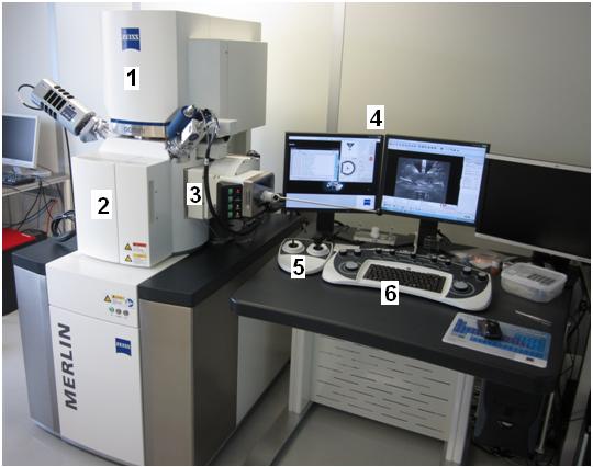
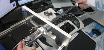
3. Semi-automatic loadlock, 4. Control monitors,
5. Dual joystick, 6. Control panel
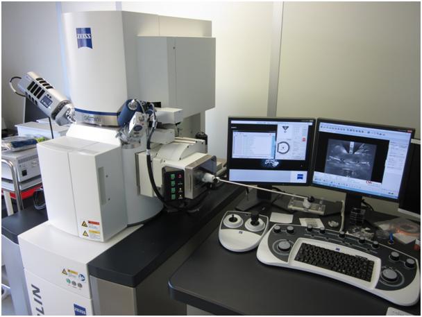
The CMi SEM MERLIN is composed of a GEMINI II column, a process chamber with a 5-axes motorized stage (X, Y, Z, Tilt and Rotation) and a semi-automatic airlock. The stage is eucentric, which means that all rotation axes intersect the same point. The specimen surface is located at the eucentric point, where the tilt axis meets the beam axis. This guarantees that the focus is maintained when the specimen is tilted at a certain working distance.
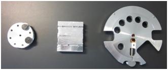
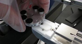
Three different holders are available: mono samples, cleaved samples and full 4inch wafer.
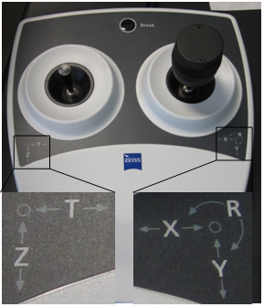
The SEM is controlled by the ZeissSmartSEM software operated via a graphical user interface. The system is also fitted with a dual joystick for stage control and specimen navigation and with a main keyboard control panel for direct access to 14 of the most frequently used functions on the SEM.
The GEMINI II column
The GEMINI II column is the area of the Field Emission SEM, where electrons are emitted, accelerated, bundled, focused and deflected. Main characteristics of the GEMINI II optics are the so-called beam booster and an objective lens that consists of a combined electrostatic/electromagnetic lens doublet.
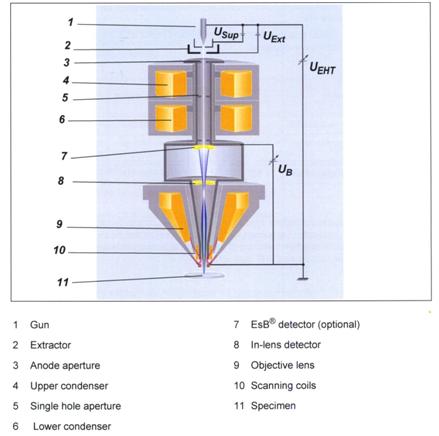
A Schottky field emitter serves as gun (1). Electrons are emitted from the heated filament while an electrical field is excited by applying the extractor (Uext) voltage. To suppress unwanted thermoionic emission from the shank of the Schottky field emitter, a suppressor voltage (Usup) is applied as well. The emitted electrons are accelerated by the acceleration voltage (Ueht).
The beam booster (Ub, booster voltage), which is always at a high potential when the acceleration voltage is at most 20kV, is integrated directly after the anode. This guarantees that the energy of the electrons in the entire beam path is always much higher than the set acceleration voltage. This considerably reduces the sensitivity of the electron beam to magnetic stray fields and minimizes the beam broadening.
| Column mode | Characteristics | Beam path |
|---|---|---|
|
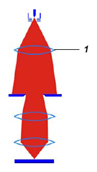
High resolution
|
The upper condenser (1) has a low excitation which is varied in order to adjust the probe current in a limited range.
|
|
|
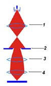
Analyzer
|
The upper condenser (1) focuses the beam and creates a crossover above the ebeam-limiting anode aperture (2). The upper condenser is adjusted to modify the probe current.
|
|
|
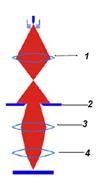
Depth of Field
|
The upper condenser (1) focuses the beam and creates a crossover above the ebeam-limiting anode aperture (2). The upper condenser is adjusted to modify the probe current.
|
|
|
Fish-eye
|
This mode enables you to view the entire 4inch wafer with electrons (EHT on). Useful for finding you sample or test patterns on the wafer |
Available detectors
The interaction products most frequently used for generation of images in scanning electron microscopy are secondary electrons (SEs) and backscattered electrons (BSEs). For that purpose, three different detectors are fitted to the system.
| Detectors | Typical application |
|---|---|
| In-Lens (annular detector) |
Surface structure |
| HE-SE2 (Everhart-Thornley detector) |
Topography |
| EsB with filtering grid (in-column detector) |
Pure material contrast |
The In-Lens detector is a high efficiency detector for high resolution SE imaging. It is located above the objective lens and detects directly in the beam path.
The efficiency of the In-Lens detector is mainly determined by the electric field of the electrostatic lens, which is decreasing exponentially with the distance. Thus, the working distance WD is one of the most important factors affecting the signal-to-noise ratio of the In-Lens. As the tilt angle of the specimen surface affects the emission angle of the electrons, you should avoid strong specimen tilting.
The HE-SE2 detector is sensitive to SEs as well as BSEs.
Electrons moving to the detector are attracted by the collector and directed to the scintillator. The collector voltage can be varied in the range between -1000V and +1000V. The collector voltage generates an electrical field in front of the detector thus directing the low energy SEs towards the scintillator. For all standard applications, the collector bias should be set at +300V. Selecting a negative collector voltage generates a field deflecting the low energy SEs so that they cannot reach the scintillator and do not contribute to the signal. Only high-energy BSEs contribute to the image generation. This produces a so-called pseudo-backscattered image, which shows pronounced topography, but largely cancels surface properties (edge contrast).
The EsB detector is an Energy Selective Backscattered detector suitable for compositional contrast. It is an annular in-column detector that is located above the In-Lens detector. It can detect SEs and BSEs.
The SEs and BSEs generated at the impact point of the primary electron beam are intercepted by the low electrical field of the column. These electrons are accelerated by the field of the electrostatic lens. A small amount of SEs passes through the hole of the In-Lens detector and would be observed by the EsB detector. To prevent detection of the SEs, a filtering grid is installed in front of the EsB detector. By switching on the filtering grid voltage, the SEs will be rejected and only BSEs will be detected. Below a landing energy of 1.5kV, the filtering grid has the additional function of selecting the desired energy of BSEs. The operator can select the threshold energy of inelastically scattered BSEs to enhance contrast and resolution.
The EDX detector is sensitive to photons. It is used to perform elemental compositional analysis.
When a secondary electron gets knocked out, an electron in a higher orbit drops down to take its place, and the excess energy gets radiated out in a form of a characteristic wavelength photon. By detecting this photon and its energy with the EDX detector, it is possible to identify the element it came from. This forms the basis of the Energy Dispersive X-ray Spectroscopy technique. Please, visit the EDX website to learn more.
The Plasma Cleaner allows to clean the sample and tool chamber by burning the carbon contamination using plasma. It is to be used by the CMi staff only. Improper or too frequent use may contribute to a degrade of the main turbo pump.
Basic operations
Starting with the ZeissSmartSEM software
First, the tool needs to be activated by logging onto CMi Zone15 computer with personal access rights.
On the SEM local computer, the Windows operating system is always open and running through standard CMi session.
The EM Server, implementing the internal communication between software and hardware, is always running too. It is sometimes minimized to a small element (icon) on the right side of the Windows task bar.
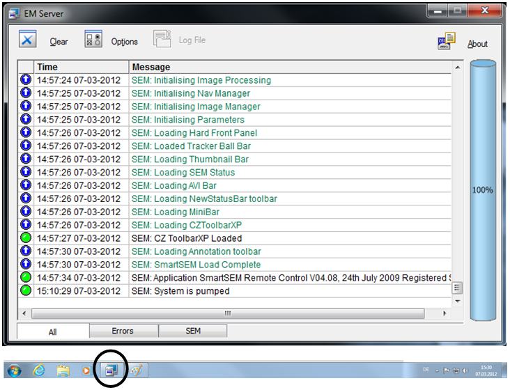
Note: If the EM Sever was accidentaly closed by the last User, Starting the ZeissSmartSEM software will first reload the EM server and recover software/hardware communication.
Double click on ZeissSmartSEM icon.
Alternatively, select Start/Programs/SmartSEM/SmartSEM User Interface. The EM Server Lon On dialogue appears.
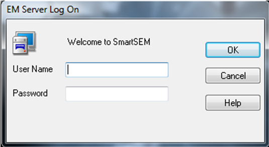
By logging, the SmartSEM user interface opens and is ready to operate the tool. By default, a TV view inside the specimen chamber is shown.
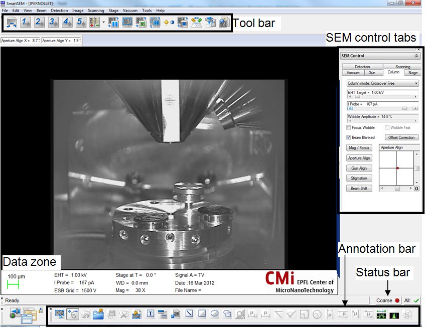
The data zone is a special and useful group of annotation objects which are used to display useful parameters. If it is not open, select View/Data Zone/Show Data Zone from the menu. Alternatively, type Ctrl+d to toggle the data zone.
All icons from the toolbar run a specific action on the tool:
| Icon | Associated function for left / middle mouse button click |
|---|---|
|
|
Live scanning / Continuous averaging 2 |
|
|
Pixel averaging 3 / Continuous averaging 4 |
|
|
Pixel averaging 6 / Continuous averaging 6 |
|
|
Pixel averaging 9 / Frame integration 5 |
|
|
Frame integration 7 / Frame integration 9 |
|
|
Specimen change via the loadlock |
|
|
Faster and slower scanning command |
|
|
Freeze-Unfreeze command |
|
|
Normal scanning command |
|
|
Reduced area activation |
|
|
Screen splitting to get two detectors viewing on the same window |
|
|
Brightness and contrast adjustment (with mouse) |
|
|
Chamber scope (TV view) activation |
|
|
Toggle In-Lens / SE2 detectors |
|
|
Magnification and focus adjustment (with mouse) |
|
|
Save image to folder |
Sample Loading
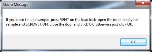
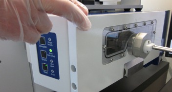
Press Exchange on the keyboard.

Follow and perform all instructions of the macro message before clicking OK. Clicking OK will start pumping the airlock and once the vacuum is reached, the loadlock will automatically open the gate.
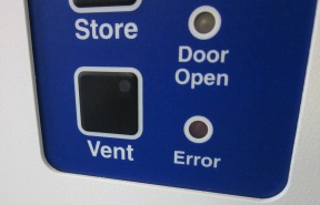
The Vent button is used to vent the loadlock with dry nitrogen. Normally it should take about 10 seconds to fully vent the loadlock which makes it possible to open the door (use handle at the bottom).
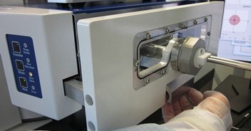
Make sure the holder is correctly loaded on the teflon railings! Be sure to screw the rod to the holder gently (use two finger only and DO NOT OVERTIGHTEN) and fully. Check that the small pin located below the rod is touching the rod. This contact completes the security circuit, without it, the gate between the loadlock and the main chamber will not open.
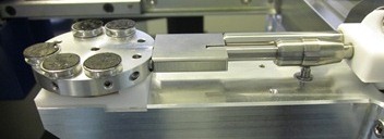
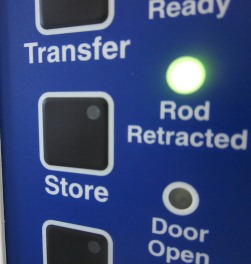
Close the door and click OK on the macro message for the pumping to start. Press the door gently towards the loadlock until you feel that the pumping has started. Check that the “Rod Retracted” green LED is lit. When correct vacuum is reached (it should take about 30 seconds), the gate will automatically open.
Check from the window when the gate is open. The light inside the chamber is automatically switched on. Load the sample onto the stage and retract the rod all the way out.
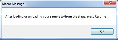
Click OK on the previous macro message and click Resume on the keyboard to close the gate.
Here, there is no need to ventilate the airlock: just click OK on this message.
Click OK on the “Resume completed” message to finish the loading sequence and to proceed with SEM imaging.
Sample Unloading
Press Exchange on the keyboard.
Click OK on the macro message (there is no need to vent the airlock now). As the loadlock is already under vacuum, the gate should open as soon as the stage move to the exchange position completes.
Check from the window when the gate is open. The light inside the chamber is automatically switched on. Unload the sample from the stage and retract the rod all the way out.
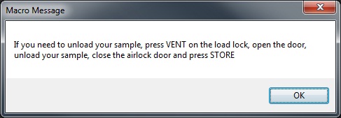
The Vent button is used to vent the loadlock. Open the door and unload the sample.
Close the door and click Store on the airlock for the pumping to start.
Validate the previous message by clicking OK.
Click OK to finish the unloading sequence.
Stage settings and motions
The Stage Navigation window can be used to initiate XY movement of the stage by double-clicking on the sample holder top view (the point where you double-click gets moved to the center). Be sure to select the correct holder from the list and to adjust the zoom view sliding bar to your needs. All five axes coordinates are reported in this window in order to save specific positioning on the sample if needed.
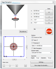
The STOP button on the Stage Navigation window or the Break button on the dual joystick can be clicked at any time to quickly stop any engaged motion of the stage.
Sample observation
The following table may help to find the required settings for your application:
| Detector | EHT | Typical WD | Detector settings | Remarks |
|---|---|---|---|---|
| In-Lens | 3kV- 20kV | 3 – 6mm | None | Avoid strong specimen tilting. Surface structure |
| 100v – 3kV | 2 – 3mm | |||
| 100V | Max 4mm | |||
| HE-SE2 | 1kV – 30kV | Min 4mm | Collector bias adjustable from -1000V to +1000V. Standard applications: +300V Pseudo BSE image: -1000V to 0V |
None. Topography |
| 1kV – 5kV | 4 – 6mm | |||
| 5kV – 30kV | Min 6mm | |||
| EsB | 1kV – 5kV | Max 4mm | EsB grid adjustable from 0V to +1500V. Value depends on type of electrons to be detected (approx.): <800V : SE +BSE >800V: BSE |
Avoid strong specimen tilting. Materials contrast |
Useful keyboard shortcuts
Ctrl + d : display/hide data zone
+ (numerical keyboard) : increase the scanning rate
– (numerical keyboard) : decrease the scanning rate
tab : fine/coarse mode
Ctrl + tab : center the sample where click on the picture
Ctrl + shift + tab : drag a rectangle on the picture and the system will automatically zoom in and center the sample into it
Ctrl + A : annotation tools