The EHN_3250 is a heat-cycle “mini” nano-imprint experiment unit, featuring a vertically air-pressurized driving cylinder and a plate heater as standard equipment.
The maximum reachable temperature is 200°C with a maximum imprinting intensity of 3kN. The maximum imprinting area is 150mm X 150mm.
Contents
I. Parts and functions
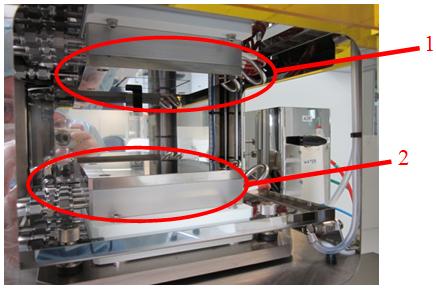
1 Head part
This part functions by an air-pressurized driving cylinder. It has a built-in plate heater.
2 Stage part
This part holds work-piece. Equipped with parallel adjustment system. It has a built-in plate heater.
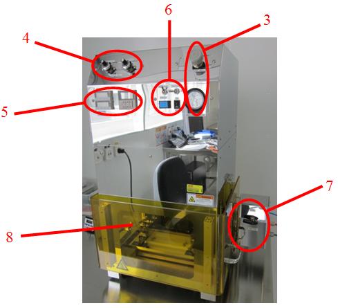
3 Cylinder pressure control part
A precision regulator controls pressure in the driving cylinder.
4 Head speed control part
This part controls the head part’s ascending/descending velocity.
5 Heating temperature control part
This part adjusts heating temperature. Capable of shutting off the heater after desired period of time by timer setting.
6 Operating part
Switches for master power ON/OFF, heater power ON/OFF and the head part’s motion controls.
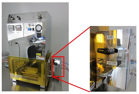
7 Cooling media selector
This part toggles cooling media (water/air) for the heated head part and stage part.
8 Safety cover
The safety cover encloses the working area and slides vertically. The head part will not descend while the safety cover is open.
II. Operating instructions
Please carefully and thoroughly read the manual and fully understand operating process before starting to use the equipment.
Do not touch the head part as well as the work stage while the plate heater is heated. You may face danger of burning.
Do not place your hand into the equipment while the head part is moving. You may get your hand caught in the equipment.
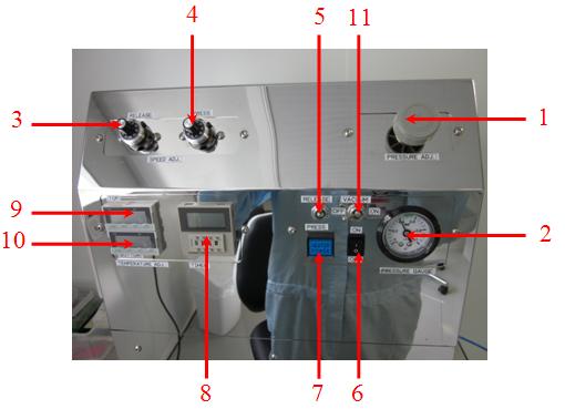
1 Pressure control handle
It adjusts head thrust by controlling pressure for the driving cylinder. To increase the pressure, turn the handle clockwise (to the right). To decrease the pressure, turn the handle counter-clockwise (to the left). The current pressure is indicated in the
Pressure gauge. Controllable range is between 0.15 and 0.4 MPa.
Tips: Set the pressure as low level as possible at the beginning, and then increase it to your desired pressure level. Please refer to the attached conversion table to find correspondence relation between set/indicated pressures and head thrusts.
2 Pressure gauge
This indicates current set driving pressure. Controllable range is between 0MPa~0.4MPa.
3 Head part’s ascending speed control knob
It trims the head part’s ascending speed. Turning the knob clockwise increases the head part’s speed as the graduated number increases.
4 Head part’s descending speed control knob
It trims the head part’s descending speed. Turning the knob clockwise increases the head part’s speed as the graduated number increases.
5 Head part adjusting lever
The lever lowers the head part down as it is pressed down. The lever lifts the head part up as it is lifted up. As long as the front door is left open, the head part will not come down even with the lever toggled. Also, notwithstanding the position of the head part, it ascends to the top end once the safety cover is open.
6 Master switch
It toggles the equipment’s master power supply.
7 Plate heater switch
It toggles power supply to the Plate heater. The lamp illuminates while the power is on. While the master switch is on, toggling the plate heater switch shuts power to the heater off.
8 Safety timer
This is a timer to prevent the Plate heater from getting excessively heated up. Power supply to the Plate heater is automatically cut off after the set periods.
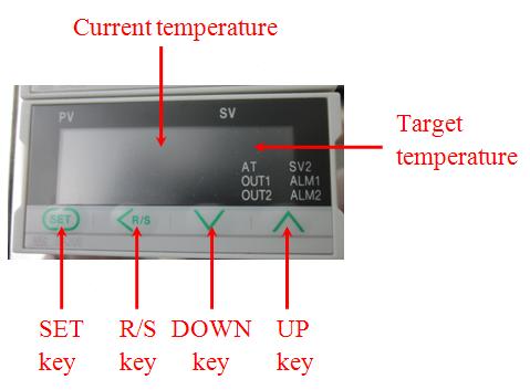
9 Temperature control unit (top side)
It adjusts temperature on the top plate heater.
10 Temperature control unit (bottom side)
It adjusts temperature on the bottom plate heater.
11 Vacuum adjusting lever: not used at CMi
The lever supplies vacuum to the vacuum groove of the head part as it is toggled right side. The lever cuts off vacuum and gives atmospheric pressure to the vacuum groove of the head part as it is toggled left side.
III. Setting the parameters
- Toggle the Master switch to ON. Each temperature control unit indicates then current plate heater’s temperature.
- Adjust pressure for the head thrust. Turn the Pressure control handle and check the Pressure gauge to set desired pressure.
- Adjust the head part’s speed. Toggle the Head part adjusting lever, the Head part’s descending speed control knob or Head part’s ascending speed control knob to adjust the head part’s speed.
- Adjust temperatures of the Plate heater. Press SET key on each unit ONCE. The digit in the one’s place flashes. Set your desired temperature by pressing UP and DOWN keys. Press R/S key to move to and set a digit in the ten’s and hundred’s places. Press SET key TWICE. The units indicate current and target temperatures.
- Set the Timer with 4 buttons located right below the timer
IV. Imprinting procedure
- Open the Safety cover, and place metal mold/die. Ball catches hold the safety cover up.
Make sure to place a work-piece in the centre of the Bottom work stage. Placed on the peripheral of the work stage, it may result in uneven imprinting. Also, it may damage the equipment. - Close the Safety cover and make sure that the Cooling media selector is at STOP. Finding the selector at other setting such as AIR or WATER, you must set it at STOP.
- Toggle the Master switch to ON.
- Toggle the Place heater switch to ON. The lamp by the switch illuminates, and the Plate heater starts to heat up.
- Once the Plate heater reaches desired temperatures, pull the Head part adjusting lever down. The head part descends and performs imprinting.
- After instructed period of time, toggle the Place heater switch to OFF. The lamp by the switch goes off, and heating terminates.
- Turn the Cooling media selector to WATER, and start cooling the equipment.
- Once the head part and work stage are cooled down enough, then turn the Cooling media selector to AIR to drain cooling water inside the equipment.
- Turn the Cooling media selector to STOP.
- Pull the Head part adjusting lever up. The head up ascends.
- Open the Safety cover and remove the work-piece.
- Close the saftey cover and turn off the machine if no more tests need to be performed.