This manual mainly focuses on how to safely set the Hardware part of the machine. Software issues as well as design making are not addressed. Please refer to T-Tech full manual for software related information.
Contents
- System features
- Initial system check
- Setting the workpiece
- Setting initial conditions
- Machining a layer
- Finishing the job
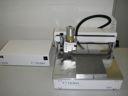
I. System features
The T-Tech QC5000S-E Quick Circuit features software adjustable motor spindle speeds between 8,000 and 24,000 RPM, making it a good fit for fast machining of various board prototypes materials. The IsoPro software enables automatic data conversion from almost any CAD package. It also offers the possibility to import DXF and export Gerber data. Main features of the T-Tech QC5000S-E Quick Circuit are:
| Min. Trace | 130um (5 mils) |
| Min. drill hole | 330um (13 mils) |
| Spindle speed | 8000 to 24000 rpm |
| Working area | 254mm X 330mm |
| X/Y positioning | Precision stepper motors |
| Resolution | 6.5um (0.25 mils) |
Some terminology before we begin:
- Work piece: the piece of plastic you are going to machine. It may also be a copper-clad board to machine printed circuit boards.
- Sacrificial board: a less expensive piece of plastic positioned under your work piece to prevent damage to the Quick circuit and breakage of carbide tips.
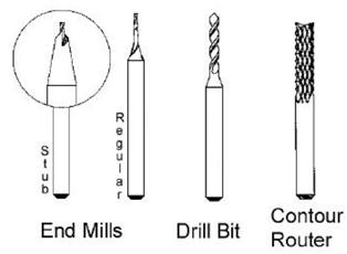
- Carbide bits: these are extremely hard tools needed for machining. There are two basic types of tools used with the Quick Circuit: end mills and drill bits.
End Mills are used to engrave patterns in the work piece or to cut through it. Lines are machined with an end mill.
Drill bits are used to drill holes in your work piece.
A significant difference between an end mill and a drill bit of the same diameter is the fact that the tip of the end mill is flat while the tip of the drill bit is pointy.
II. Initial system check
Verify the status of the Quick Circuit system first by performing the following checks:
- Log on CMi login system.
- Verify that the USB cable between the computer and the CNC is connected in both ends.
- Verify that the milling table is connected to the controller with the 37-pin cable.
- Verify that the vacuum system is plugged into the controller and connected to the head assembly of the milling table. Make sure the switch is ON in the vacuum unit.
- Verify that the Top Stop and the vacuum hose underneath the milling head are both raised enough to prevent the Quick circuit from hitting any obstacles during initialization.
- Turn on the controller, then turn on the computer (computer might be on already).
- Double-click on the IsoPro icon on your desktop.
- Initialize the milling table by selecting Mill > Initialize from the menu bar. The Mill will now move all the way to the lower right corner of the table and then move to and stop above the HOME position (0,0).
III. Setting the workpiece
Setting up your plastic pieces in the Aluminum holder
- Some plastic pieces of standard dimensions are at disposal. These pieces are 1mm thick, 25 mm wide and 75 mm long and feature four alignment holes. The centers of these 1.5 mm holes are positioned 2.5 mm from the edges of the plastic piece. The plastic is currently PMMA. Other choices of plastic may become available in the future.
- An aluminum holder capable to contain 8 plastic pieces is also at disposal. The holder features two parts, a thick base and a thin top clamp. The clamp can be secured to the base using M3 torx conical screws.
- A sacrificial plastic piece must be positioned underneath your working PMMA piece to prevent damage to the aluminum holder.
- Once all your PMMA working and sacrificial pieces are in place, secure the top clamp using the screws.
- Select Mill > Material Change to move the head of the Quick Circuit away and position and secure the aluminum holder on the table of the Quick Circuit using the two holes on each end of the holder.
- Verify that neither the head nor the carbide tool (if any is mounted) hit the aluminum holder while moving. Refer to Section 3 to set the upper limit of the head.
Pinning a board
Note: this section may be skipped if the aluminum holder is used or if a working piece is already properly placed and pinned on a sacrificial board.
The quality and precision during your cut is highly determined by the precision used in creating your pinning holes.
NO MACHINING IS ALLOWED WITHOUT THE USE OF A SACRIFICAL MATERIAL UNDERNEATH.
This backup material may be used a few times before flipping it over to the other side. The material should be replaced by a new piece when more than 60% of the total surface area has been machined on.
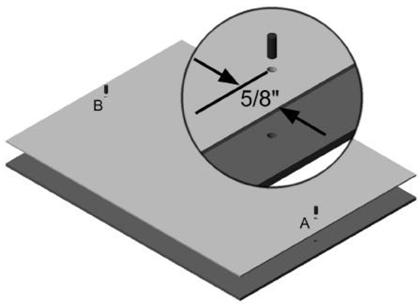
- Begin by adhering a piece of double sided adhesive on your sacrificial piece. Position your work piece on top of the sacrificial piece and press them together. The backup material should cover and protect the entire area beneath your working piece.
- Now you will drill both pieces, working piece and sacrificial board, through to create your pinning holes (A and B in the figure below)
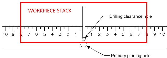
- Position your sacrificial, working piece stack on the Quick Circuit table. Center the stack around the (0,0) position as shown below:
- Double-click on the IsoPro icon on your desktop.
- The drilling clearance hole is located at the absolute HOME (0,0) position on the milling table. This should be verified in order to prevent accidental drilling into the table top. Select Mill > Home which will move the head to (0,0).
- Select Mill > Tool Change from the menu bar. The head will move out towards you leaving a clearance to change the carbide bit.
- Loosen the chuck’s set screw and place the STANDARD DRILL BIT, a 3.175 mm or 1/8” diameter bit, in the chuck. Push the bit inside the chuck until it stops. Tighten the chuck’s set screw.
- Click OK in the dialog box to return to your previous position. Make sure the head moves back to the HOME (0,0) position. If the head does not move to Home, repeat Step 3.
- Select Mill > Jog. A dialog box appears with the manual controls of the Quick Circuit (see figure below):
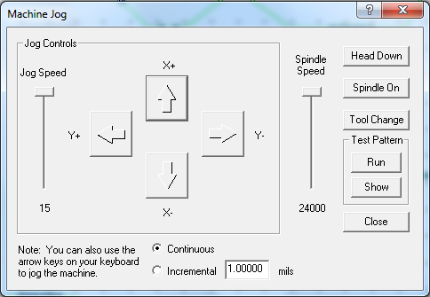
- The chuck must be centered above the drilling clearance hole at HOME position before continuing:
Set Spindle speed to 24000 RPM.
Click on Spindle ON and wait 5 seconds.
Click on Head Down to drill your pinning hole.
Once the drill bit has gone through both plastic pieces click on Head Up.
Once the head is up, Click on Spindle OFF.
- Rotate your stack 180° to drill another pinning hole (hole B) on the other end of the stack.
Note: The exact positioning of the holes in the board is not critical. What is important is that the holes be drilled cleanly so that the dowel pins fit tightly into the holes. Holding the board and backup material firmly while drilling helps to ensure precision locator holes.
- Placing a Board on the Milling Table:
Go to Material Change position by selecting Mill > Material Change. The head will move to one of the upper corners to let you position your board on the table. Place the pinned working piece-sacrificial board stack on the milling table with one of the extended dowel pins in the primary pinning hole and the second pin in the groove that runs down the middle of the milling table. Make sure your working piece is facing up. You may secure the left and right edges of the board and backup material down with masking tape. This adds to the stability and accuracy of the system.
IV. Setting up initial conditions
Setting the Upper Travel Limit
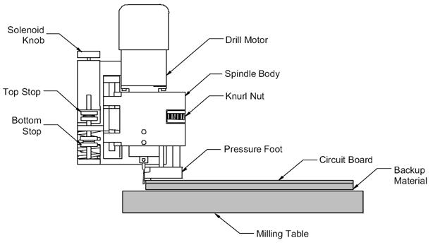
A pair of thumb nuts is provided to set the Top Stop position. The lower nut will set the location; the upper nut will lock the nuts in position.
The Top Stop setting will also allow the operator to limit the amount of upward travel of the solenoid plunger. Insufficient solenoid force to start the downward motion during machining will result from too large solenoid top extension, e.g. greater than 5 mm.
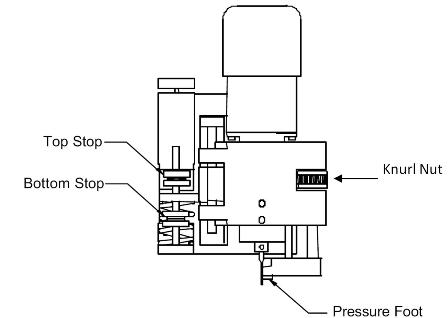
Setting the Lower Travel Limit
The lower travel limit can be set by the Bottom Stop thumb nuts or by the Pressure Foot:
When using the Bottom Stop thumb nuts, the upper nut will set the location; the lower nut will lock the nuts in place. When you use the bottom stop thumb nuts make sure to move the pressure foot all the way up to avoid restricting downward movement of the head assembly
The pressure foot can be moved up and down using the Knurl nut. When you use the pressure foot, move the Bottom Stop thumb nuts to the extreme down locked position to avoid restricting the downward movement of the head assembly.
V. Machining a layer
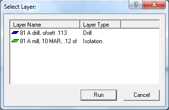
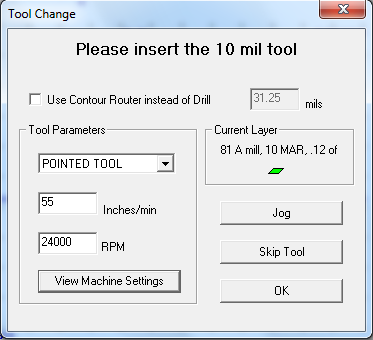
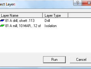
Select Mill > Run Layer. The head moves to the Tool Change and a dialog box showing the different layers in your file appears. Select the layer you want to mill or drilled. After you select your layer a ‘Tool Change’ dialog box appears.
- Use the 1,6 mm (1/16″) Allen wrench to loosen the set screw on the chuck. The tool should then fall out of the chuck. Extreme caution is advised as these tools are delicate and can be easily broken through mishandling.
- Store the removed tool in its corresponding box.
DO NOT MIX THE TOOLS as it can be hard to recognize the exact diameter by only visual inspection! (can you tell a 250 um tool from a 300 um one?). - Place the new tool bit in the chuck insuring that the tool is seated completely up in the chuck (push up until it stops). While holding the bit in place, tighten the set screw with the Allen wrench. The tool can be held in place comfortably using two fingers. Avoid putting pressure from the bottom as you could easily break very small tools this way.
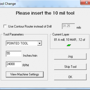
- Select the right tool in the drop down menu in the dialog box. Select either end mill or drill bit according to the tool you just installed.
- Input the milling speed and spindle rate as follows:
Type of bit Speed (in/min) Spindle rate (rpm) End Mill 2 17000 Drill Bit 1 24000
The speed during milling must be kept low when machining thick substrates to prevent breaking the tool. Higher speeds can be used when milling depths <0.25 of the end mill diameter.
Verify the correct values are input (type of tool, speed and spindle rate). - Adjust the tool height and depth of cut for the current operation (drilling, milling) every time you change the tool.
YOU ARE NOT ALLOWED TO INITIATE MACHINING WITHOUT VERIFYING THE TOOL HEIGHT AND DEPTH OF CUT.
Setting tool height
The procedure to set the height of a tool above your circuit board will be the same regardless of the type of tool or spindle assembly used.
Click on Jog in the dialog box.
- Use the arrow keys to position the head just next to the edge of your working piece-backup material stack. Make sure your carbide tool comes down along the edge of the stack.
- Using the Top Stop thumb nuts, position the bottom of the tool just slightly above (about 1mm) the working piece. Verify the carbide bit will not hit your working piece at any point.
By keeping the tool as close as practical to the board material, you will greatly increase tool life and accuracy. This is due to the velocity with which the tool hits the board material when using a solenoid configuration. The higher the tool starts above the material, the greater the solenoid will accelerate the tool before entry into the board material.
This acceleration increases the chance of the carbide tool chipping or breaking. A good rule is to place the 1,6 mm (1/16”) Allen wrench flat on the board material next to the bit.
Then adjust the Top Stop to have the tool’s height above the board material to be less than the thickness of the Allen wrench.
Setting depth of cut for drilling
After loading the correct drill or mill, set your depth of cut. When milling thick pieces, you will have to run the same layer several times to cut through your working piece. As a rule of thumb you can only cut as much as the diameter of the endmill in one single pass, e. g. if you are using the 3.175 mm end mill you can only cut as much as 3.175 mm into the work piece. You will break the tool if you attempt to cut deeper. This problem is not so critical when using the drill bits. You can drill through a thick piece at once with most drill bits. When drilling you want the bit to drill completely through the work piece and slightly into the backup material.
To the right side of the spindle body is the Knurl nut (nut with ridges). Below this nut, is the pressure foot. The pressure foot rides along the surface of the material on the milling table. This allows you to set the tool depth of cut accurately with regards to the material’s surface. Otherwise slight warps in the material would influence your depth of cut.
Turning the ridges on the knurl nut to the left as you face the head (or clockwise if you are looking down on it) will raise the pressure foot thereby increasing your depth of cut. The Knurl Nut has clicks or detents in it. Each detent moves the pressure foot up or down by 0,010 mm (0.0004”) increments.
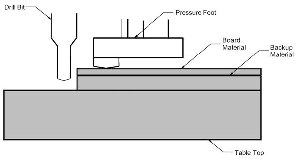
- Press down manually on the head assembly.
- Rotate the Knurl Nut until the point of the drill bit is below the bottom of the work piece when the pressure foot is flush against the board material.
Note: A practical limit of the thickness of the workpiece is around 8 mm.
Thick pieces (> 2mm) require the milling to be conducted in several runs of the same layer.
Now that your upper and lower limits are set double check the type of tool, speed and spindle rate. If everything is set correctly you can click on Run.
Note: You can abort the cutting at any time by pressing the red button on the controller unit. The system will stop and you must then re-initialize everything.
VI. Finishing the job
After you are done machining all your layers, you must remove all tools and your workpiece (or aluminum holder) from the Quick Circuit.
- Select Mill > Tool Change. Remove the carbide tool as specified above and store the tool in its correspondent case. Click OK.
- Select Mill > Material change.
- Remove your workpiece or aluminum holder from the Quick Circuit table.
Note: You can leave the working piece-sacrificial board stack assembled for future users. Just leave the stack in the same place of the plastic stock.
- Use the vacuum cleaner in the room to remove plastic chips from the table of the Quick Circuit, the head and all the surroundings, including the floor.
- Select Mill > Home. The head moves to position (0,0).
- Turn off the controller, exit IsoPro, Log Off from your account. Place all tools and used material inside the plastic box on top of the controller.