Aim
|
|
Provide DSOs with information on the various elements at both LV and MV levels of the grid and grid’s status and decentralized production and consumption; and tools for fault location, isolation and services restoration. |
Activities
There are two sets of PMU activities undertaken in the frame of the REeL demo:
a) The PMU hardware adaptations
b) The PMU algorithm improvement
The PMU hardware adaptations
The aim of this set of activities is to adapt the existing synchrophasor technology (i.e., PMUs and Phasor Data Concentrator (PDC) previously developed by the EPFL-DESL) to the specific needs and operating conditions of the medium voltage grids in Rolle. The following approach is undertaken:
a) Definition of sensing technology candidates based on installation constraints;
b) Definition of candidate PMUlocations based on targeted applications;
c) Development of a “PMUkit” in order to facilitate the installation phase;
d) Development of a PDC to be installed in electrical substations.
The PMU algorithm improvement
This set of activities complements the abovementioned on the PMU hardware adaptation and aims to update the PMU software and adapt it to the specific challenges (such as big-data analysis) and needs (such RTSE functionality) of the demonstration sites. Furthermore, it focuses on the visualization of the results. Therefore, the following approach is undertaken:
a) Development of network models for power flow studies
b) Development of a synchrophasor big-data analysis software
c) Experimental validation of the Real-time state estimation functionality
d) Development of a user interface that enables the visualization of real-time and historical measurements/estimations
Preliminary Results
The 1st prototype is under development and the PMU infrastructure will be up and running by end of the year.
Up to date, the voltage/current sensing infrastructure has been defined. It consists of:
- Clamp-on current sensors based on the Rogowski coil technology (see Figure 1) installed in every substation owned by Romande Energie and measuring both current flows and injections/absorptions;
- Pluggable voltage sensors based on capacitive divider technology (see Figure 1) installed in the substations measuring nodal voltages.
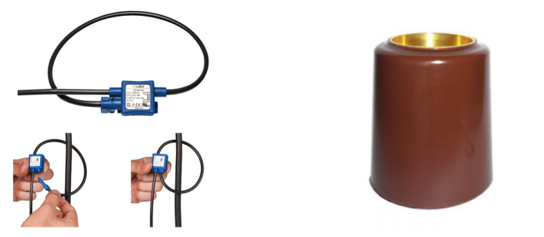
Figure 1: Selected sensing technology: clamp-on current sensors (left) and pluggable voltage sensors (right)
Furthermore, the PMU software and related performance has been further improved as reported on the table below:
Table 1:PMU performance improvement.
|
|
Now |
Before |
|
Sampling rate |
50 kHz |
50 kHz |
|
Max. # of input ch. |
24 |
18 |
|
Reporting rate |
50 Hz (typical), 500 Hz (max) |
50 Hz (max) |
|
Window length |
1÷5 periods at f0 (user selectable) |
3 periods at f0 (fixed) |
|
Latency (total) |
<1ms |
<15 ms |
|
DFT latency |
25 ns/DFT bin |
0.4ms/DFT bin |
|
i-IpDFT latency |
50 us/channel |
50 us/channel |
|
Waveform recording: |
COMTRADE standard |
None |
In order to improve the reliability and connectivity as well as the synchronization capabilities of the whole system, the existing PDC and Real-Time State Estimation (RTSE) code has been optimized and integrated into a ruggedized (fanless) industrial controller from National Instruments (IC-3173). Also, the PDC has been coupled with a time-series database (InfluxDB) and a multi-user, web-browser accessible HMI (Grafana) capable of visualising both real-time and historical data (see Figure 2).
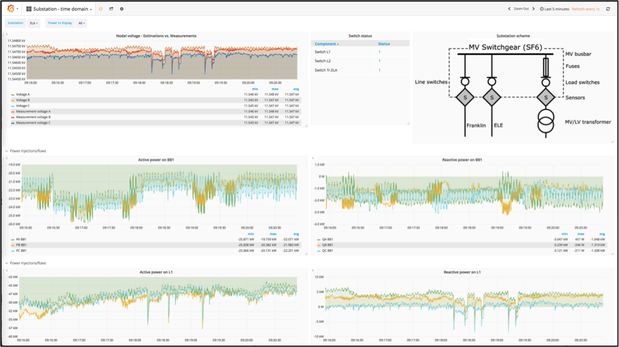
Figure 2: Visualisation of real-time and historical data
Involved partners/Contacts
 |
|
 |
References
Derviškadić, A., Romano, P., & Paolone, M. (2018). Iterative-Interpolated DFT for Synchrophasor Estimation: A Single Algorithm for P- and M-Class Compliant PMUs. IEEE Transactions on Instrumentation and Measurement , 67 (3), 547 – 558. https://infoscience.epfl.ch/record/233662