Research Domains
@copyright 2023 EPFL Alain Herzog
EPFL Institutes
EPFL institutes are principal organisational units housing the various disciplines in which EPFL’s research enterprise is active. Institutes belong to one or two of EPFL’s Schools, and are listed below in alphabetical order.
Discover all Institutes
Civil Engineering Institute (IIC)
Environmental Engineering Institute (IIE)
Institute for Area and Global Studies (IAGS)
Institute of Architecture (IA)
Institute of Bioengineering (IBI)
Institute of Chemical Sciences and Engineering (ISIC)
Institute of Electrical and Micro Engineering (IEM)
Institute of Mathematics (MATH)
Institute of Mechanical Engineering (IGM)
Interschool Institute Neuro-X (INX)
Management of Technology & Entrepreneurship Institute
Swiss Institute for Experimental Cancer Research (ISREC)
EPFL Research Centers
EPFL’s Centers build research communities and foster synergies across disciplinary boundaries within the EPFL research enterprise, provide open research platforms that offer access to major research infrastructure, and house research initiatives common to EPFL and other institutions within or beyond the academic world.
Discover all Centers
EPFL Facilities I Technology Platforms
EPFL Facilities provide access to cutting-edge research infrastructure and expertise to EPFL scientists and students. They are also a place where knowledge and knowhow is shared and where EPFL contributes to advance the state of the art in the techniques covered by each shared facility.
Discover all Facilities
Material
Molecular and Hybrid Materials Characterization Center
X-Ray Diffraction and Surface Analytics Platform (ISIC-XRDSAP)
Crystal Growth and Characterization Plateform
Chemistry
Central Environmental Laboratory
Mass Spectrometry and Elemental Analysis Platform (ISIC-MSEAP)
Nuclear Magnetic Resonance Platform (ISIC-NMRP)
Life science
Biomolecular Screening Core Facility
Bioelectron Microscopy Core Facility
Bioengineering & Technology Facility
Mechanical
Student Kreativity and lnnovation Laboratory
Plateforme Ateliers Techniques
Atelier de Fabrication Additive (Impression 3D)
Atelier de fabrication de Circuits Imprimés.
Atelier de l’institut de génie mécanique
Atelier de l’Institut de production et robotique
Atelier de l’Institut des Matériaux
Electronic and Mechanical Engineering Workshops Platform
Bio – Micro – Nano
Center of MicroNanoTechnology (CMI)
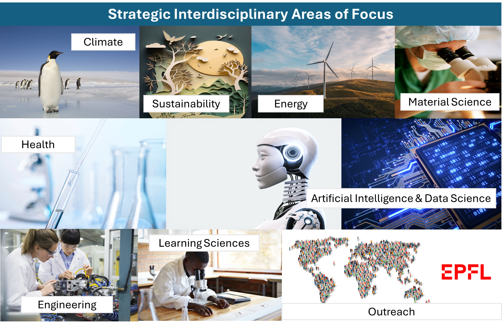
Interdisciplinary Focus Areas
Interdisciplinary Focus Areas pool the expertise of EPFL scientists on crucial topics that drive the institution’s strategic research agenda and address global challenges and foster innovation.