The characteristics of the SDSS-V project
SDSS-V is an all-sky, multi-epoch spectroscopic survey that will yield optical and IR spectra of over 6 million objects during its five year observing-time (2020-2025). Using SDSS’s existing and anticipated new facilities at Apache Point Observatory and Las Campanas Observatory, SDSS-V will survey the entire sky — mapping the Milky Way using rapid, repeated observations, mapping Local Volume galaxies using wide-angle integral field spectroscopy, and mapping black holes using time domain spectroscopy of quasars and bright X-ray sources.
Instead of SDSS’s classic plugplate system, SDSS-V will use a new, custom-built robotic positioning system developed by EPFL to allow for rapid configuration of fibers. These fibers will lead to the existing APOGEE and BOSS spectrographs, enabling simultaneous IR and optical observations. In addition, a new wide-field integral-field units will be deployed to observe the stars and interstellar medium in the Milky Way, Magellanic Clouds, and local galaxies such as M31 at unprecedented spatial resolution.
SDSS-V comprises three key programs, called Mappers:
-
The Milky Way Mapper (MWM) will target 4-5 million stars across the Milky Way, collecting infrared spectra with an APOGEE spectrograph and/or optical spectra with a BOSS spectrograph. The MWM seeks to understand the evolution of the Milky Way, the physics of its stars and interstellar medium, and the architecture of multiple-star and planetary systems.
-
Using the BOSS optical spectrograph, the Black Hole Mapper (BHM) will target over 400,000 X-ray selected Active Galactic Nuclei (AGN). These sources that harbours supermassive black holes (SMBH) will be selected from the eROSITA space mission. Many of these AGNs will be observed numerous times, with the goal of measuring black hole masses, probing black hole growth across cosmic time, and characterizing the X-ray sky. Other ancillary targets will be observe in parallel to the AGNs and includes galaxies part of X-ray cluster or other interesting and rare extra-galactic sources.
-
The Local Volume Mapper (LVM) will observe the interstellar medium and stellar populations in the Milky Way and several local galaxies, collecting more than 25 million contiguous spectra over 3,000 square degrees on the sky. The LVM will use new integral-field spectrographs to explore the physics of star formation and the interactions between stars and the interstellar medium.
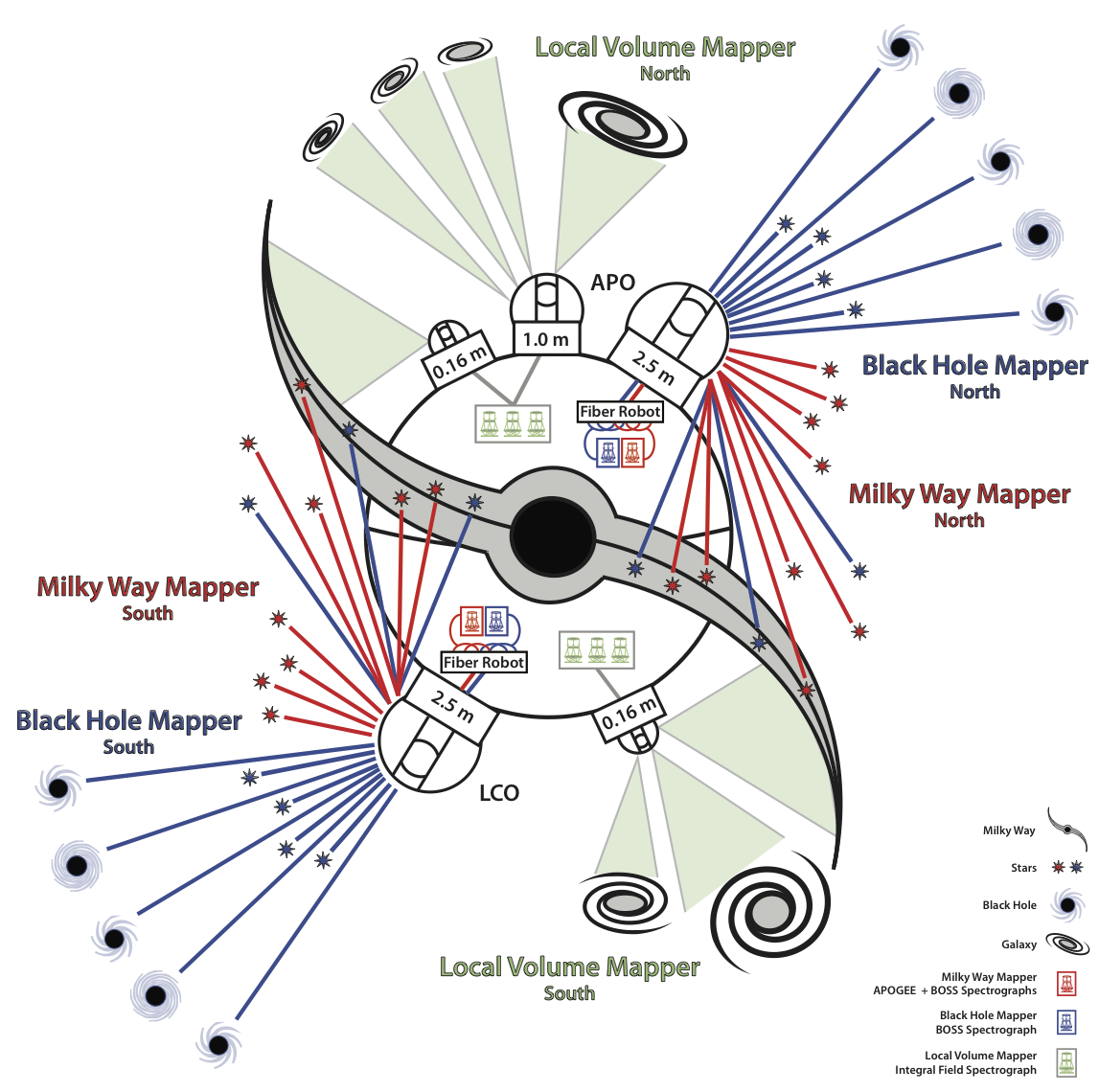
SDSS-V will be carried out in both hemispheres, at Apache Point Observatory (APO) in the USA and Las Campanas Observatory (LCO) in Chile. Multi-object fiber spectroscopy will be obtained with two 2.5m telescopes, each feeding a near-infrared APOGEE spectrograph and an optical BOSS spectrograph, for the Milky Way Mapper and Black Hole Mapper programs. The Local Volume Mapper will make use of smaller telescopes at APO and LCO to perform its optical integral-field spectroscopy. Image credit: M. Seibert (OCIS) & SDSS-V team.
The Fiber Positioning System (FPS)
The past decade has seen an enormous investment by the astronomical instrumentation community in massively-multiplexed robotic fiber instruments. Systems becoming operational in the next few years use many thousands of actuators. These include DESI (5’000 robots, first light end of 2019), PFS (2’400 robots – 2020), VLT/MOONS (1’000 robots – 2020), and 4MOST (2’400 spines – 2022).
Development of sophisticated fiber configuration and collision-avoidance software has proceeded apace with mechanical developments, and a few groups – including EPFL – have partnered with industrial firms to address the non-trivial logistics of mass-production and quality control of the positioners.

The SDSS-V FPS is a conservative instrument: adapting existing solutions and leveraging on OSU, UW and EPFL/Astrobots previous experiences with DESI and MOONS. Our design philosophy is to preserve the field of view and basic position and focus accuracy of the current SDSS plug plate system, use the existing spectrographs, telescope interfaces, and handling fixtures with minimal modification, and re-use/adapt the cartridge architecture and fiber infrastructure where practical.
The goal is to develop and deploy by end 2020 a robotic fiber positioner system (with 500 robots each) on both the 2.5m Sloan telescope at Apache Point Observatory (APO) in New-Mexico and on the 2.5m Irenee du Pont telescope at the Las Campanas Observatory in Chile.
The SDSS-V FPS organization, schedule and milestones
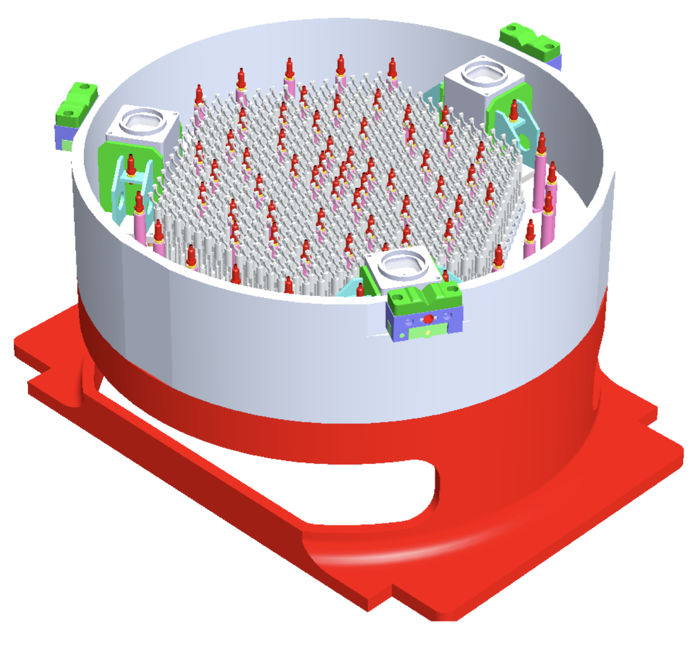
Each FPS unit has 500 zonal fiber positioners arranged in a hexagonal array, each carrying a science fiber for the BOSS spectrographs, and a subset of 300 carrying a second fiber for the APOGEE spectrograph. The distribution of the 300 APOGEE fibers among the 500 positioners is optimized to maximize the common field of view.
The positioner array is interspersed with a set of field-illuminated fiducials to establish a fixed reference frame against which fiber positions are measured with a fiber viewing camera. The basic layout of the FPS focal plane in shown in Figure 3.

FPS focal plane layout showing positioners (colored + and annuli), fiducials (blue & white circles), and guide camera locations (black squares). Gray and red transparent circles show the patrol fields of each positioner. The large red dashed circle is the field of view of the current generation plug plates.
The baseline concept for the FPS consists of these primary subsystems:
Fiber Positioner Robots (FPRs) – EPFL
Two sets of 500 fiber positioners arranged in a hexagonal pattern with overlapping patrol fields carrying 2-3 fibers each. The positioners is designed by the EPFL Astrobots group and will be build in partnership with an industrial company.
Optical Fiber Assemblies (OFAs) – University of Washington
The visible and near-infrared optical fibers that run from the positioners to the BOSS and APOGEE spectrographs, plus room for a third metrology fiber that can be back-illuminated for the Fiber Viewing Camera (FVC) system.
Guide/Focus/Acquisition (GFA) Cameras – Ohio State University
At least three imaging cameras mounted around the periphery of the positioner array to provide images of the night sky to guide, focus, and alignment.
Field Illuminated Fiducials (FIFs) – Ohio State University
These are fixed illuminated pinhole projectors distributed across the focal plane to provide a precise reference coordinate system.
Mechanical Structure & Thermal Enclosure – Ohio State University
This is the mechanical structure that carries the fiber positioners with their optical fiber assemblies, FIFs, and GFA cameras on a curved plate matching the telescope focal surface. It is surrounded by a thermal enclosure that has the same basic envelope as the current SDSS cartridges and re-uses existing telescope latching interfaces and handling equipment (e.g., the Lindy Cart).
Fiber Viewing Camera (FVC) – Ohio State University
This is a camera and optical system mounted above the primary mirror that images back- illuminated science fibers and the FIFs for fine alignment of the science fibers.
Instrument Electronics Box (IEB) – Ohio State University
This is an outboard box mounted next to an FPS on the telescope that distributes switched power and ethernet to FPS onboard systems, provides environmental monitoring (temperature and humidity) inside the thermal enclosure, and carries point-of-use control computers for the GFAs and the fiber positioners.
The fiber positioner robots design of the EPFL team
The fiber positioner robots design for the SDSS-V project has been iterated from prototype “P0” (completed early 2018) to prototype “P1” (completed in December 2018). Figure 2 gives the cut-out view of the P1 mechanical design. The construction of the P1 prototypes and their evaluation has allowed us to define a reference design that is presented in this call of tender for the manufacturing of the 2×550 fiber positioners.
3D cut view of the P1 prototype design.
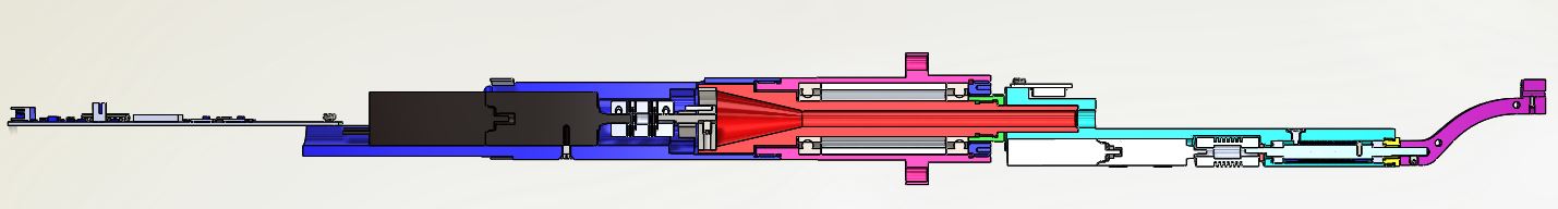
Although we are providing a baselined concept, the vendor has the freedom to propose an alternative design based on our baseline concept. What it is key is that the requirements listed are guaranteed by the industrial manufacturing process.
As explained below, following the Kick-off meeting and the evaluation of the design, we expect the vendor to produce a pre-series of 30 positioner robots before launching the complete manufacturing process. This pre-series will be evaluated by EPFL to validate the concept of the vendor. EPFL will evaluate the robots as soon as they are produced and made available by the vendor. Once the robots are compliant with the requirements, the mass production can start, this will be decided following the Evaluation Review and the Production Review.
We expect the delivery of the 2×550 fiber positioners in a minimum of two batches starting end 2019 till June 2020 following the schedule indicated below (Section 6 of the Characteristics and Requirements Document).
Providers can obtain general information on the laboratories involved in this research from the internet address http://astrobots.epfl.ch/