Overview of Data Recording
We record human data from 19 subjects recruited from ETVJ in total. Among these subjects, 12 are students in the 1st and the 2nd year of the school. We consider these students as novice subjects. We keep tracking of the learning progress of these subjects and record their watchmaking manipulation every semester (three semesters so far). The other seven subjects comprise five students from the 3rd and the 4th year, as well as two teachers of the school. These seven subjects are considered as expert subjects. We record both motion and tactile information from human subjects. We use data recorded from expert subjects as baselines to evaluate the performance and assess the improvement of novice subjects.
Motion Segmentation
The recorded videos of human subjects are manually segmented and labelled based on the meaning of the motion. Labels of motion segments include:
- Tool Selection: subject selects tools (e.g. tweezers, pegwood, screw-driver) for performing the task;
- Adjustment of Hand Pose/Watchface: subject adjusts hand poses or orientation of watch face before task execution;
- Localization: subject moves hands to localize the tips of tools towards the desired location, e.g. to pick up the component;
- Pick and Place: subject uses tools to pick and place used watch component (e.g. screw, plate, spring) to its target position, either on the watchface, or on the table surface;
- Execution: subject executes the required assembly/disassembly task.
The segmented motion lists of each subject’s data recording are available on GitHub and also Zenodo (Sensor Recording and Motion Segmentation).
Modelling of Human Hand
Manipulation motions of human subjects are captured by recording the movement of hand markers using camera array. Taking advantage of the reconstructed marker trajectories, we construct kinematic model of human hand to analyze the hand poses and finger motions of subjects during manipulation task.
The model include two parts:
- Kinematic Model: a 21-DoF kinematic model for analyzing the static hand pose (determined by finger joint positions);
- Animation Model: a model constructed by recorded hand trackers for visualizing the hand movement.
A simple example to use the model is given in the main file of both packages. These models are available at:
https://github.com/epfl-lasa/SAHR_database/tree/master/Code/Hand%20Model
In addition, the SynGrasp toolbox is also used for the analysis of hand poses. This MATLAB toolbox is available at:
http://sirslab.dii.unisi.it/syngrasp/?p=247
Data Visualizer
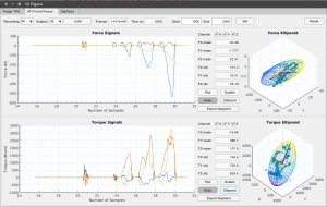
Tactile information are recorded during experiments. This data visualizer allows users to easily visualize the recorded tactile information data in the project, including:
- Finger pressure information, recorded by the FingerTPS sensors;
- Force/torque applied on the watchface, recorded by the ATI Force/Torque sensor;
- Pressure applied to the tweezers, recorded by the DigiTacts system.
It also provides several data analysis functions, such as:
- Calculating signal features (mean, standard deviation, amplitude etc.);
- Fitting signals using 3D force/torque ellipJournals
Yao, K. and Billard, A. An inverse optimization approach to understand human acquisition of kinematic coordination in bimanual fine manipulation tasks. Submitted to Biological Cybernetics, 2019. Under review. The datasets generated during and/or asoid (or 2D ellipse); - Visualizing correlation coefficient matrix of signal sequences.
Introduction to installing and using this application can be found on the following page.
GitHub link: https://github.com/epfl-lasa/SAHR_database.git
Learning Dynamical Systems With Bifurcations
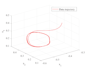
This MATLAB/c++ package provides tools for:
- finding parameters of a dynamical system with bifurcation from data trajectories via optimization (MATLAB folder);
- controlling a robot’s end effector with the learned DS (cpp folder, as a ROS node);
- modifying the parameters of the DS during operation.
GitHub link: https://github.com/epfl-lasa/SAHR_bifurcation
Link for abstract of paper “Learning Dynamical Systems with Bifurcations”, Lauzana, I. and Billard, A. (submitted to RA-L): https://github.com/epfl-lasa/SAHR_bifurcation/Abstract_RA-L_paper.pdf
Learning Lyapunov-type energetic functions for multiple attractors dynamical systems
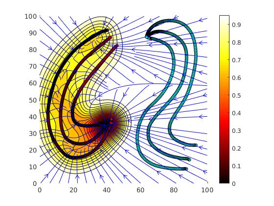
This MATLAB package provides a tool for:
- Clustering sub-dynamics of multiple attractors dynamical system from unlabeled training data (position and velocities) of demonstrated trajecotries;
- Attractors’ position identification in a so-called embedding space;
- Reconstruction of plausible Lypaunov-type energetic functions through weighted sum of kernels.
GitHub link: https://github.com/epfl-lasa/SAHR_multids
Miscellaneous
The datasets used in the study of “An inverse optimisation approach to understand human acquisition of kinematic coordination in bimanual fine manipulation tasks” is available on GitHub and Zenodo.
The datasets collected in the study of “Hand Pose Selection in a Bimanual Fine-Manipulation Task” is available on GitHub and Zenodo.
Audio and Tactile dataset of robot object manipulation with different material contents
The dataset captures the auditory and tactile signals of a Kuka IIWA robot with an Allegro hand holding a plastic container containing different materials. The robot manipulates the container with vertical shaking and rotation motions. The data consists of force/pressure measurements on the Allegro hand using a Tekscan tactile skin sensor, auditory signals from a microphone, and the joints data of the IIWA robot and the Allegro hand joints.
The dataset is available on here DOI:10.5281/zenodo.6372437.
The work was funded by the CORSMAL project and ERC SAHR project.
Benchmark for Learning and Control of Bimanual Insertion of Semi-deformable Objects
Here we provide information and data required to replicate the benchmark setup and evaluation protocol.
Abstract
We propose a new benchmarking protocol to evaluate algorithms for control and learning of bimanual insertion of irregularly-shaped and semi-deformable objects. The benchmark is inspired from watchmaking craftsmanship. Watchmaking takes years of training, during which trainees learn to coordinate their two hands to assemble tiny watch pieces precisely. The benchmark offers to insert the plate, an irregularly shaped object which needs to be correctly oriented prior to insertion. It must then be held stiffly in place by one arm, while the other inserts it by slightly bending the semi-deformable plate’s leg. The benchmark requires two robotic arms with at least 4 degrees of freedom. Force/torque sensing is not required but likely of benefit. We provide CAD drawings of the watch pieces that can be easily 3D printed to ensure ease of reproduction. The pieces are scaled to fit the workspace of the usual robotic set-up sizes. We offer a detailed description of the task and of the protocol for successful reproduction. We also provide meaningful metrics for reasonable comparisons in the field. We provide two different versions of the metrics in order to evaluate motion planning and learning algorithms, both independently and jointly.
CAD Files and Physical properties
You can download the CAD files (STEP files) of the watch parts here. We also include the physical properties of the individual objects in case one wants to use them in simulation. URDF models will also be available soon (with the physical properties already set).
3D Printing details
We expect the potential users of the benchmark to 3D print them using technologies similar to FDM for watchface and SLA for other components. Choosing 3D printing technologies depends on user’s preference and potential; however, the only constraint is that the technology must have precision up to 1mm for watchface and 0.5mm for other components.
Computer Vision Baseline Code
As part of the benchmark we provide a baseline code for inferring the relative transformations between the objects using ChArUco markers and computer vision. The code is based on OpenCV and python (a C++ version will be available soon). Link to code to be added soon..
ChArUco markers setup
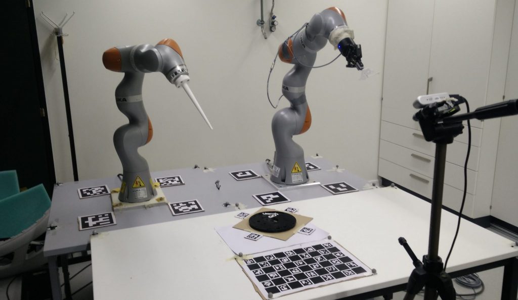
In our setup, we use a single camera to detect all ChArUco markers. The camera is placed on the opposite side of the two robot arms. It is placed roughly in the middle so most markers are visible.
Four markers from the same ArUco dictionary are placed around each robot arm and the watch face, as shown in the picture. Each group of four markers muct form a perfect square.A ChArUco chessboard is not required but might help for calibration reasons. Each robot arm, watch face, and chessboard is associated with a unique ArUco dictionary. Within an ArUco dictionary, each marker is assigned to an index label. Specifically, in a group of four ArUco markers, the IDs assigned are 0, 1, 2, and 3. OpenCV algorithm can detect these markers and output their corresponding IDs. Please note that same IDs are shared across different ArUco dictionaries (i.e. there is a 0-indexed marker in every group of four markers, and same applies for the other markers). This is a nice feature to reduce complexity when we need to address orientation of the markers.
In our setup, markers are placed in clockwise order according to their IDs, starting from ID 0. There is no specific orientation for the markers surrounding the watch face, since all four markers are visible to the camera. However, for the markers surrounding the robot arms, the marker in the back corner may be occluded by the robot arm. Thus, our computation requires only three markers to be visible for each robot arm. This requires us to enforce a specific orientation of markers: the marker labeled with index 0 is always placed in the bottom left corner. Using three markers per robot and specific orientation, we can construct the coordinate frames correctly.
Metrics and Details
Here we provide details about the metrics and how to determine failure cases. Details to be added..
Code for Dual-Arm Centralized Control
To define the QP control problem we use our whc C++ library. The exact code used for our baseline experiments will be available soon..