Biological Electron Microscopy Facility
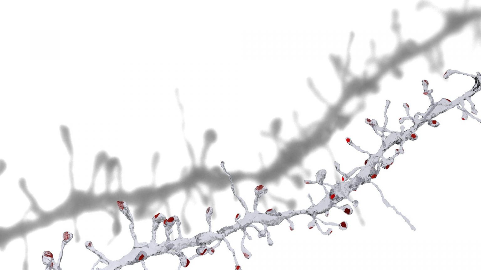
3d reconstruction of a dendrite showing spines and their synapses (in red). This work was done as part of a project carried out for Sami El Boustani (University of Geneva), and published in Science in 2018.
The BioEM Facility is a laboratory specialising in the preparation and imaging of all types of biological samples using scanning and transmission electron microscopy. The laboratories are part of the School of Life Sciences, and located in the AI building. For any enquiries about sample preparation, imaging, and training please contact any of the BioEM staff.
Who we are
Who we are and how to get help with your electron microscopy project
Techniques
We provide a range of techniques for imaging biological samples with transmission and scanning electron microscopy
Resources
The equipment and facilities that we have available to us.
Latest news
Reimagining the shape of axons
In a collaboration with the group of Shigeki Watanabe from Johns Hopkins University School of Medicine, the BioEM facility used a cryo preservation method to reveal the true shape of axons in the brain. This work, published in Nature Neuroscience showed that unmyelinated axons of the mouse central nervous system have nonsynaptic, nanoscopic varicosities ~200 nm in diameter repeatedly along their length interspersed with a thin cable ~60 nm in diameter like pearls-on-a-string.
Commentary articles: SciTech Daily; Neuroscience News; Science; Medical News
From flagellate to amoeba – mechanisms of flagella removal
In a study published in the journal EMBO Reports, scientist Alexander Woglar from the group of Professor Pierre Gonnczy in collaboration with the BioEM facility has shown how a single cell organism is able to eliminate the structures that comprise the flagellar structure, therefore transforming from the flagellate to an amoeboid life form. This study used serial section transmission electron microscopy correlated with light microscopy.
Exploring bacterial defence mechanisms
Nicholas Flaugnatti from the group of Professor Melanie Blokesch has shown in the journal eLife how the cell envelope of bacteria and specifically the capsular polysaccharide (CPS) can affect the functionality of a secretion system that is used to breach this barrier. Changing the amount of this polysaccharide can further impair this functionality. This work used transmission electron microscopy to image the bacterial cell wall.
Graham Knott, office AI0143
tel: +41 21 6931862