Wind Tunnel Experiments

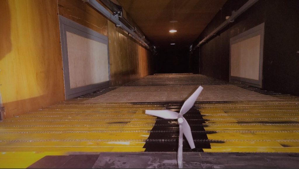
At WiRE, laboratory-scale experiments are performed on especially designed wind turbine models in a boundary-layer wind tunnel using state-of-the-art flow measurement techniques. Contrary to field measurements, wind tunnel experiments offer full control over the flow conditions and experiments can be designed to study different flow problems in a systematic fashion.

Wind tunnel experiments
WiRE Wind tunnel test section

Recent Research

Ongoing experimental research at WiRE involves an array of topics which have gained popularity within the wind energy community in recent years. These include (but are not limited to) active yaw control, vertical axis wind turbine wakes and wind turbine wakes in topography.
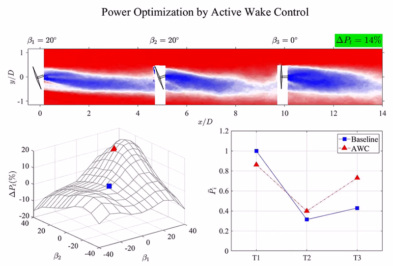
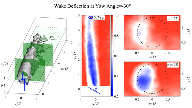
Active Yaw Control

Active yaw control has emerged as a promising strategy for improving the power yield on a wind farm level. By actively yawing a wind turbine away from the incoming wind, the wake is deflected away from the downwind turbines. At WiRE, we perform wind tunnel experiments on the power performance and wakes of wind farms subjected to this strategy. These experiments provide new insights into the flow physics of the wake deflection and serve as a basis for theoretical models. Using these experiments, our experts have also developed yaw optimization algorithms for wind farm control.
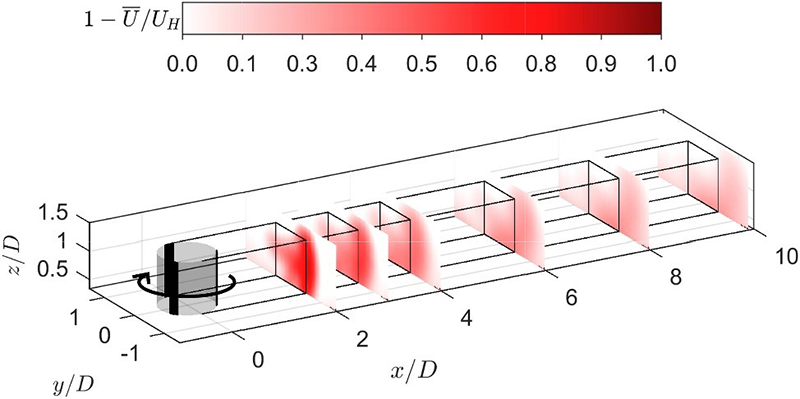
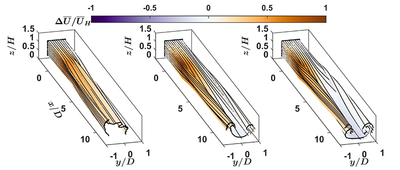
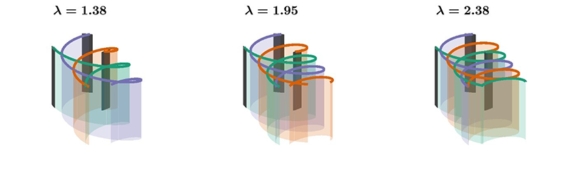
Power Gain Achieved A Specific Yaw Control Setup For An Aligned Wind Farm
Power gain achieved by a specific yaw control setup for an aligned wind farm
Deflection Of The Wake
An instantaneous flow field obtained using tomographic PIV showing the deflection of the wake

VAWT Wakes

Vertical axis wind turbines have been underexplored historically. These turbines have, however, regained interest from the wind energy community due to their potential advantages over their horizontal axis counterparts. Our research focuses on experimental investigation of VAWT wakes under variety of different operational conditions and development of analytical models for the wake of these turbines.

VAWT Wake
Contours of the normalised streamwise velocity deficit in the wake of a VAWT
VAWT Streamtubes
Streamtubes of the mean flow through the variably-pitched vertical axis wind turbine for increasing tip speed ratios, (left) λ=1.28, (middle) λ=1.95, (right) λ=2.33. A counter-rotating vortex pair is produced as a result of trailing tip-vortices. The strength of vortex pair increases with increasing tip speed ratio
VAWT Tip Speed Ratio
As a blade travels around the periphery of the rotor, it sheds a continuous vortex sheet of horseshoe vortices into the flow. A quasi-continuous vortex sheet can be observed on one side of the rotor where the blades travel upstream. On the opposite side of the rotor, the blades shed ‘loops’ of vorticity as they travel downstream. As the tip speed ratio increases, the ‘loops’ become more tightly packed. This is likely the cause of the strong counter-rotating vortex pair observed at higher tip-speed ratios.

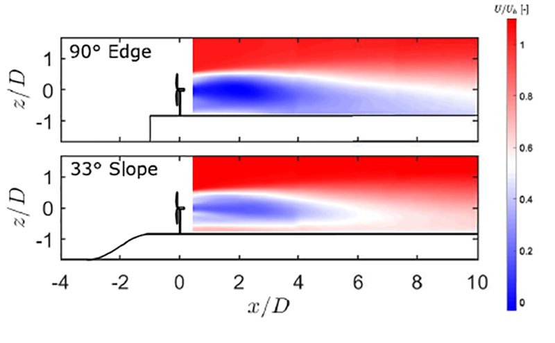
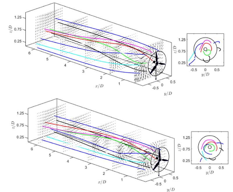
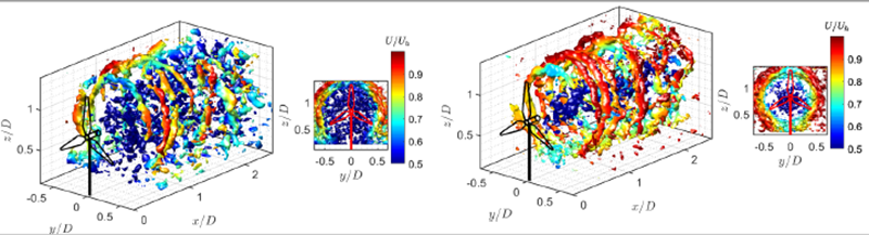
Wind Turbine Wakes in Topography

Onshore wind energy is one of the cheapest available energy resources in the world. Wind turbines on land are often sited on complex topographical features. The choice of topography as a site is made either to take advantage from the flow speed-up across hills or due to a lack of better alternative. Flow over topography is highly dependent on the geometrical details of the terrain and complex flow features, such as flow recirculation, lee waves are a common observation. The interaction of wind turbines and their wakes with these complex flow characteristics is far from understood.

Our research focuses on unravelling the complex nature of physics that arises from the interaction of flow with wind turbines in topography.

Topography
Contours of the normalised averaged streamwise velocity in the wake of a turbine sited on a 90° Edge (top) and 33° slope (bottom) escarpment. The wake is observed to be much stronger for the turbine sited on 90° Edge escarpment than that on the 33° slope escarpment. The inflow conditions are same for both cases.
Streamling Tracing
Streamlines tracing the mean flow trajectory in the wake of the turbine sited on 90° Edge (top) and 33° slope (bottom) escarpments. In-plane velocity vectors are displayed at selected planes parallel to the rotor plane. Side panels show the front view of the three-dimensional plot. The wake rotation can be observed to be comparatively stronger for the turbine on the 33° slope escarpment.
Vorticity ISosurface
Isosurfaces of the instantaneous vortices identified by Q-criterion for the turbine sited on 90° Edge (left) and 33° slope (right) escarpment. The isosurfaces are colored by the instantaneous normalized streamwise velocity. The tip vortices are observed to be stronger for the turbine on the 33° slope escarpment compared to that on the 90° Edge escarpment. Hub vortex is intact in the right panel, whereas it is broken in the left panel.