First make sure you’re using the right board marked with “Ver. 2.1“.
In general we call a shield an additional board that can be added to expand the microcontrollers functionality. A commonly used shield for example is a little screen to display some values. In the case of the Kit PRism, the shield contains a Serial interface, a chip that manages the motors of the robot, commonly known as an H-Bridge, and if you want to build the additional expansion of the Kit PRism, there’s space for a Bluetooth module.
Like the PRismino, all the components of the shield can be found in the tray labelled “pièces kit PRisme”. please keep it tidy.
Table of components
As a quick overview, here is the list of all the components you’ll need. make sure to get them all at once, it’s a terrible idea, you’ll end up wasting time trying to identify the components
| Component | Value |
| C1 | 10 nF |
| C2 | 10 uF |
| C3 | 2.2 uF |
| R1, R2, R3, R4 | 10 kΩ |
| R5, R6 | 1 kΩ |
| LED | 0805 |
| Component | Quantity |
| 8 pin female connector long | 2 |
| 6 pin female connector long | 2 |
| 2×3 female SPI connector | 1 |
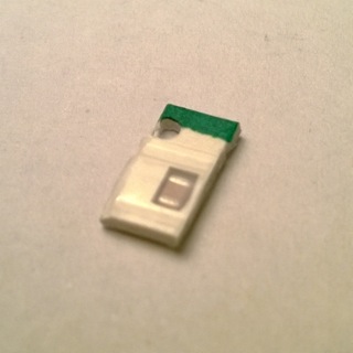
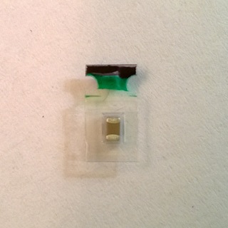
| 3 pin female green connector | 1 |
| I2C connector | 1 |
| 2×3 pin male servomotor connector | 1 |
| blue potentimeter | 1 |
| 1×2 male pin jumper | 1 |
| blue connectors | 2 |
| buzzer | 1 |
| push button | 1 |
Assembly guide
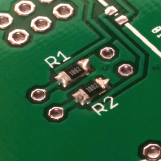
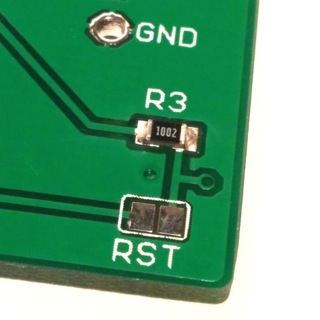
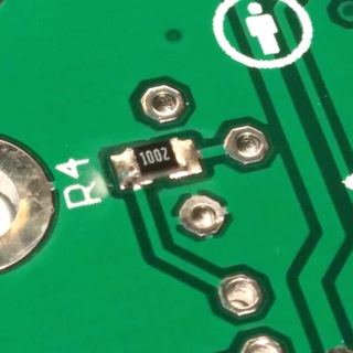
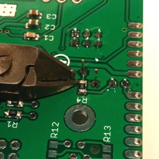
Step 1: Dip switch resistors R1, R2, R3, R4
Solder the resistors R1, R2, R3, R4 labelled 1002 (10 kΩ) in place. If you can’t find their places, you might want to check the other side of the PCB. R1 and R2 serve as pull-down resistors for the 2 dip-swithces, R3 and R4 serve as protections from shshort-circuits
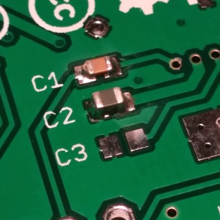
Step 2: Capacitor C1
Now you’ll need to solder in C1 which should have a value of 10 nF.
i don’t know what high-side gate voltage drive is
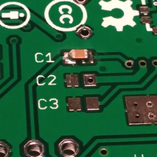
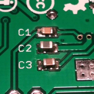
Step 3: capacitor C2
Put the capacitor C2 in place. its value should be 10 μF. this capacitor serves the purpose of smoothening the input voltage of the H-bridge.
Step 4: Capacitor C3
Solder in C3 with the value 2.2 μF. Again this one serves to smooth out the inputs.
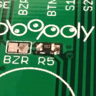
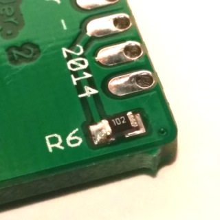
Step 5: Solder R5 and R6
now solder in R5 and R6 with the value 102. R5 protects the buzzer. R6 protects the led on the shield.
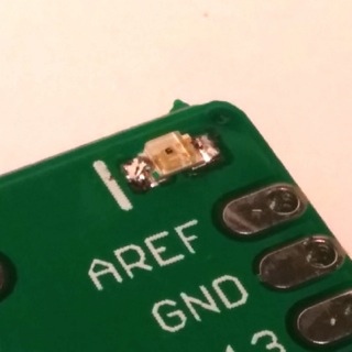
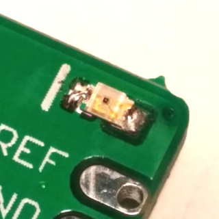
Step 6: LED
solder in the LED. make sure again the either the dot or the triangle are oriented towards the white line. leds or more generally diodes have a direction in which they conduct pretty well and one in which they don’t conduct.
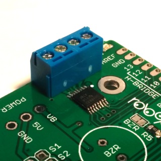
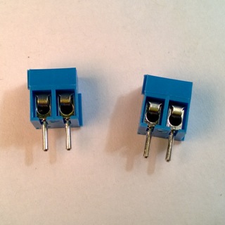
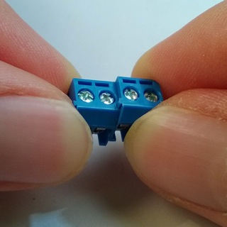
Step 7: blue connectors
get the blue connectors. Watch out for the joint between them, you should assemble them before soldering them in. Also make sure to solder them in on the top side of the shield, the side of the microchip.
Step 8:
Solder the 2×3 male pins on, they allow external access to the motor although we will not be using them.

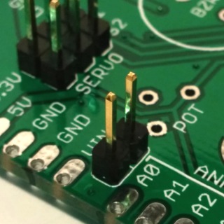
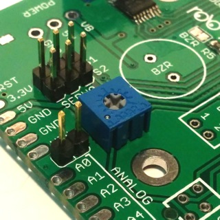
Step 9: potentiometer jumper
Instead of using a switch to enable the potentiometer, we add in a jumper, which is just a much simpler version of a switch. solder in a 2×1 male pins connector such that we can add a jumper on it.
Step 10: the potentiometer
Solder in the potentiometer and cut off its leg.
potentiometer leads to analog in 0, don’t know what it’s supposed to measure though
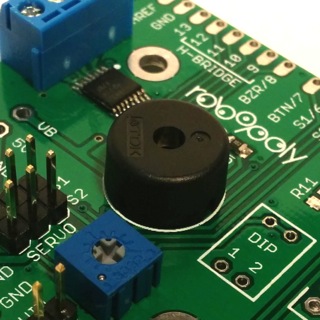
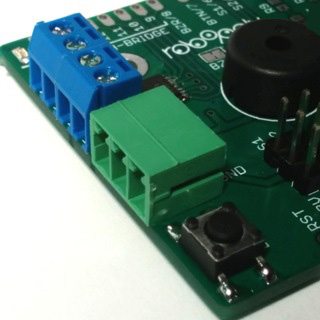
Step 11: solder in the buzzer
the buzzer is a buzzer, it buzzes. solder it in and cut its legs. the orientation is not relevant.
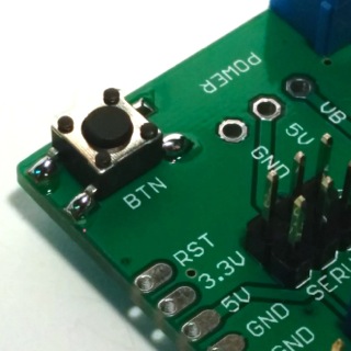
Step 12: Push Button
Solder in the push button.
Step 13: green power connectors
solder in the green 3x female power connector. this will deliver the power to the boards
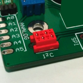
Step 14: I2C connector
solder in the I2C connector. I2C or I²C is a communication protocol between multiple devices. A protocol is the equivalent to a language but for circuits. if circuits don’t talk the same language, nothing’s going to work.
Step 15: 6 and 8 bit connectors with long legs
Now we finally get to the part that makes this circuit a shield. solder in the female connectors with long legs. make sure the legs are straight, the goal is to connect the two boards via these long legs poking through the PCB. don’t cut them off!
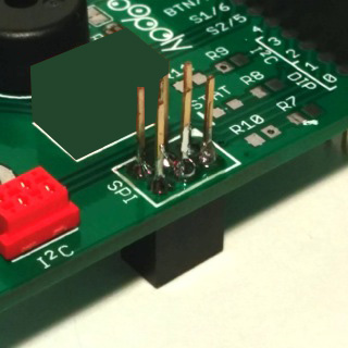
Step 16: SPI connector
solder in the spi connector. this connector will align with the male pins if the spi connector on the PRismino. make sure to have the black side of the connector below the board on the side where the long legs of the previous connectors stick out. the legs of this connector should be facing upwards.
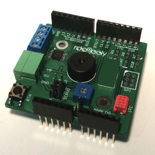
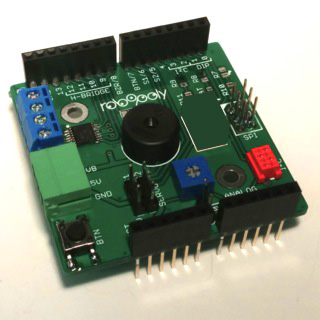
Step 17: put it on top of your PRismino, it’s done!
Now you can connect the two boards by stacking them. The communication between the board happens through the SPI connection. Using the long legged pins, you still have access to all the pins. Most pins have been matched to a function, therefore, when programming your board, you should not change their function.
| A0 | Potentiometer |
| D0 | Bluetooth (RX1/DIP1) |
| D1 | Bluetooth (TX1/DIP2) |
| D2 | I2C (SDA) |
| D3 | I2C (SCL) |
| D5 | Servo 2 (S2) |
| D6 | Servo 1 (S1) |
| D7 | Button (BTN) |
| D8 | Buzzer (BZR) |
| D9 | Motor |
| D10 | Motor |
| D11 | Motor |
| D12 | Motor |
| D13 | LED |
Programmation Guide
In the following example we’ll be making music using a library developed by robopoly.
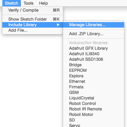
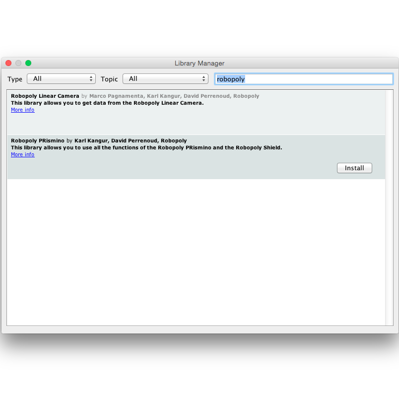
Step 1: setting up the library
First open the arduino IDE, go to Sketch > Include Library > Manage Libraries… and search for “robopoly”. Instal the library called Robopoly PRismino.
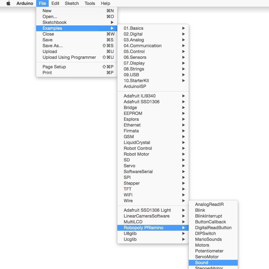
Step 3: executing
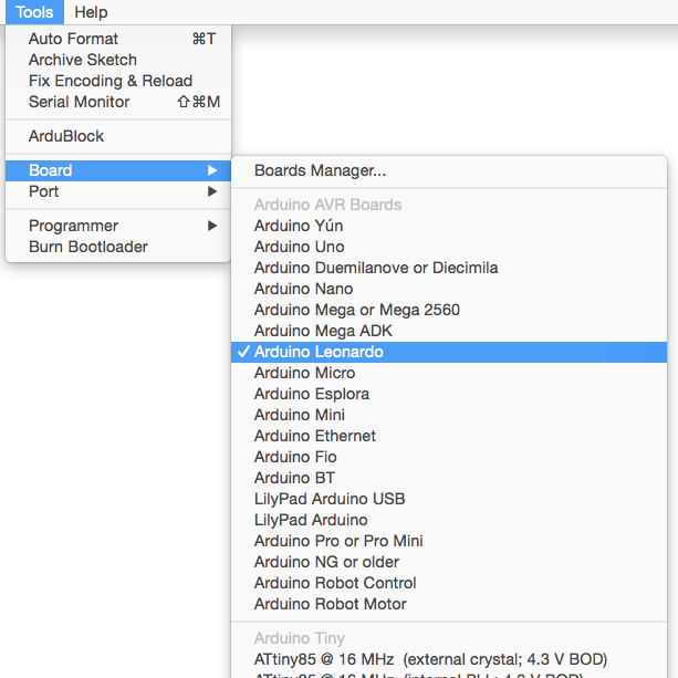
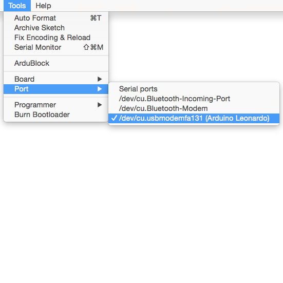
Now connect your board, go to Tools > Board > Arduino Leonardo to tell your compiler what board you’re using. Go to Tools > Port and choose the right port. Compile and Upload the code to your board. once uploaded, it should start making music!
Next: Power board