The majority of atomic force microscopy experiments are performed in air, but the tapping-mode detection speed of current high-speed cantilevers is an order of magnitude slower in air than in liquids. Traditional approaches to increasing the imaging rate of atomic force microscopy in air have involved reducing the size of the cantilever, but further reductions in size would require a fundamental change in the detection method of the microscope.
We showed that high-speed imaging in air can instead be achieved by changing the cantilever material. We use cantilevers fabricated from polymers, which can mimic the high damping environment of liquids. With this approach, SU-8 polymer cantilevers were developed that have an imaging-in-air detection bandwidth that is more than an order of magnitude faster than those of conventional cantilevers of similar size, resonance frequency and spring constant.
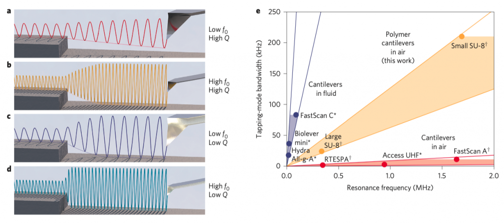
Why are polymer cantilevers faster? An oscillating cantilever subject to a boundary condition change (Figure 1, a) has a response time related to the ratio f0/Q. Both increasing the resonance frequency f0 (b) and decreasing the Q factor (c) lead to similarly improved response times. Using small, high-f0, low-Q polymer cantilevers maximises f0/Q for the fastest cantilever amplitude response in air (d).
Trends (e) in the development of cantilevers for HS-AFM imaging in fluid and air. Increasing the resonance frequency of a cantilever in fluid strongly increases its imaging bandwidth because the cantilever Q is low in the high damping environment (blue lines). For traditional cantilevers in air, however, an increase in f0 only has a marginal influence on the imaging bandwidth (red lines), because the Q remains high in the low damping environment. Using polymers as a cantilever material greatly boosts the cantilever bandwidth in air (yellow lines), because the large internal cantilever damping yields a low Q in any medium.
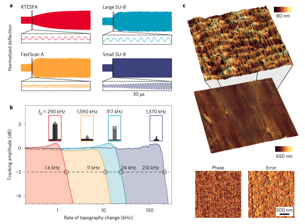
Figure 2 shows HS-AFM tapping-mode imaging in air using small SU-8 cantilevers. a, Cantilever amplitude response to a step increase in drive amplitude. The time taken to reach the steady state is related to the ratio f0/Q. b, Response of the cantilever amplitude to surface height modulation. The −3 dB frequency of the small SU-8 cantilever is increased by a factor of 19 compared with a conventional AFM cantilever of similar size, resonance frequency and spring constant. c, High-resolution overview imaging of a Celgard membrane at a tip surface speed of 261 μm s–1, maintaining good tracking. The overview image has dimensions of 8,192 × 3,200 pixels and the digital zoom-ins 656 × 256 pixels, all in the same region. Error scale: −2 to 2 nm; phase scale: −8 to 8°.
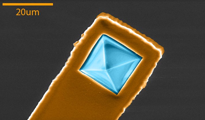
A remaining issue with polymer cantilevers are the tips. Making the tip of the cantilever out of polymer does not meet the requirements for tip sharpness and durability. Merging the high imaging bandwidth of polymer cantilevers with making sharp and wear resistant tips is essential for future adoption of polymer cantilevers in routine AFM use. In recent work (under review) we have developed a batch fabrication process to integrate silicon nitride tips into high-speed SU8 cantilevers (Figure 3).