Grayscale lithography creates three-dimensional microstructures with height gradients in a low-contrast positive photoresist (i.e. series ma-P 1200G). The exposure depth is precisely controlled by modulating the laser intensity. The latter is converted into exposure depth and subsequently into resist topography on the microscale.
The system tools use a process called 8-bit grayscale. The design is exposed to the photoresist eight times with eight different intensities, where the smallest bit is worth 0.39 % of the base dose. The next bit is worth double the bit to its right until the 8th bit, which itself is worth 50 % of the base dose.
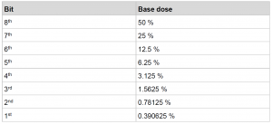
The combination of these 8 bits, corresponding to 8 exposed designs, allows for up to 256 distinct grey intensity levels that will transfer into the resist to create a 2.5D profile. For example, here is a potential stair design that we could try to expose.

There are many different possibilities for the machine/operator to expose this design. Here is a possibility of a bits combination to create the various doses and the corresponding designs.
The layer exposed with a dose corresponding to the first bit covers the whole surface. The next 3 bits should not be exposed on the outer parts of the design. Finally, bits 5 to 8 are exposed only in the center.

Training
We are offering a training of ~30-60min to any person trained on the MLA and who wants to use the grayscale capabilities of our MLA-2.
Before the training, you can already look at the following document created by HIMT.
The information in the next section are here to give you a few more information on the process and have an overview of what will be done.
In practice
- Create your design in DXF or Bitmap (8bit) format. Each layer or color will correspond to a dose (i.e. a depth/height).


- Determine the link between thickness after development and dose :
You can use the following design to determine the thickness obtained by 256 levels with the Filmetrics F54 : CMi Greyscale DoseTest
-
- MaP1275-G : 1500RPM, SB = 15min@105°C, Relaxation = 20min, Laser 405nm – 100%, Dev. time = 9min

- MaP1215-G : 3000RPM, SB = 90s@105°C, no Relaxation, Laser 405nm – Filter10%, Dev. time = 90s

- MaP1275-G : 1500RPM, SB = 15min@105°C, Relaxation = 20min, Laser 405nm – 100%, Dev. time = 9min
- Create the dose map :
Each layer will be assigned a bit (which corresponds to a dose). This assignment is quite restrictive on which doses are possible. Here is how it work :
- The operator determine a Base Dose, let’s take 1024 as an example.
- The MLA assigns a dose to each bit in the following manner :
Step = Base dose / 8bit = 1024 / 256 = 4
Max dose = Base dose = 1024

- In X-Convert (the conversion software), when importing a DXF-Greyscale file, you will be able to define for each layer which bit you want to assign them (i.e. which dose) → the Graytable
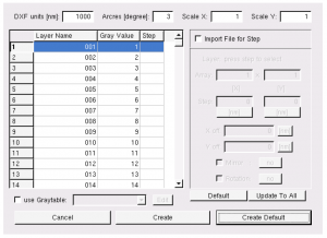
You will be able to define this manually or by importing a Graytable (i.e. similar to a text file).
- To characterize your results, SEM and optical profiler (e.g. Bruker Contour-X) are suitable options.

- Then it is a matter of iteration to make the design you want. Good luck 🙂
Alignment
The MLA150 menu does not allow you to align your substrate in the same way as with binary lithography. However, there is a workaround that is not too time-consuming. Here’s what you need to do:
1. Load your wafer (and do not unload it until the end)
2. Determine the rotation offset
Proceed with a normal alignment strategy to determine the rotation offset of your loaded wafer. Any settings will work in the layer definition, as nothing will be exposed.

3. Go back to the main menu
Click on Setup Job

4. Open your design in KLayout and rotate it by the measured angle
Keep the sign of the measured angle and convert it from [mRad] to [deg]. Rotate your design using a shape that is centred at (0;0), fully symmetrical and larger than your design, to ensure that the axis of rotation is at (0;0). Typically, a circle of the same size as a wafer and centered will do the job.
5. Convert the rotated design
6. Create a new alignment setting with only one coordinate taken from the rotated design
Avoid coordinates that are too close to the center and ensure that the rotation has changed the coordinate from those of the original design (if not, repeat step 4 or check if you are measuring on the correct design).
7. Repeat Steps 1-2 to correct the position offset (no need to measure the angle)
8. Define the First exposure layer with your rotated design (step 5) and expose it
In theory step 7 has corrected the offset and step 4 the rotation