Step 2: Explanation of the circuit and choice of components
Circuit

The circuit was made on EasyEDA.
Explanation of choice of circuit components
We decided to make a 3×3 macropad because it’s a good number of buttons; there aren’t too many or too few.
There are two ways to connect the switches: either by assigning each switch a pin on the microcontroller or by creating a matrix.
The first option is good if there aren’t many switches.
- Simplification of the circuit
- Better responsiveness: Each button is read directly, without the need for polling, which reduces latency.
- Simultaneous key detection: Avoids the limitations of “ghosting” and “key rollover” on matrix keyboards.
- Ease of programming: Each button can be handled independently, simplifying the input handling code.
- Less CPU consumption: no need to scan a matrix regularly, which can be useful for resource-constrained microcontrollers.
The second option is necessary when you have a large number of switches. It’s the most common.
There are two main ways to detect which key is pressed in a keyboard matrix. The first, which is the most common, involves scanning the rows or columns one by one. A voltage is applied successively to each row (or column) and, in parallel, checks which columns (or rows) have recorded a connection. Thus, when a key is pressed, it establishes contact between a row and a column, allowing its precise position to be identified. This scan is repeated rapidly to continuously update the keyboard’s state. This method is advantageous because it optimizes power consumption and reduces the load on the microcontroller by activating only part of the matrix at a time.
A second approach involves applying voltage to all rows or columns simultaneously. When a key is pressed, the system quickly scans all columns or rows to detect where the connection has been made. This method can provide faster detection, but it can also result in higher power consumption and require more complex microcontroller management.
In general, the first method is preferred for its simplicity and efficiency, while the second can be useful in specific cases requiring ultra-fast detection.
Diodes are also used to prevent ghosting (the phenomenon where some keys fail to register when multiple keys are pressed simultaneously). I chose 1N4148 SMD SOD-123 diodes, which are commonly used because they are very fast and reliable.

Matrice 3×3
There are three different types of switches:
- Linear: appreciated for their silence and responsiveness, the switch glides smoothly.
- Tactile: you feel a slight vibration-like feedback (between linear and clicky).
- Clicky: an audible “click,” with audible and tactile feedback.
There are several brands of switches: Cherry MX, Kailh, Gateron, Flaretech, Razer, Logitech, Roccat, etc. I decided to go with Kailh box white switches . To be able to easily change the switches according to the preferences of the people building the kit, we decided to use hot-swap switches, which allow the switches to be attached without having to solder them, making them easy to change.
For the keycaps, you also need to make sure they are compatible.
On the macropad, I also wanted:
- a rotary encoder to control the volume (this rotary encoder doesn’t need to be directly connected to a power supply).
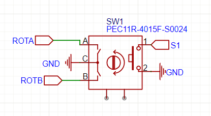
Pins A and B of a rotary encoder are quadrature signal outputs, used to detect rotation and direction of movement (time-shifted square signals). This shift is used to determine the direction of rotation. If A changes before B → Rotation in one direction. If B changes before A → Rotation in the other direction
- An OLED screen to display text or small images (I2C)
- RGB LEDs for visual appeal. We considered putting LEDs under the switches, but instead opted for a different look with LEDs under the circuit board.
For the microcontroller, I chose an Arduino Pro Micro based on the ATmega32U4 (5V/16Mhz). It’s small, recognizes itself directly as a HID (Human Interface Device), and can power everything. We decided not to use female headers, which would prevent us from directly soldering the microcontroller to the PCB, as that would take up more space.
Finally, to flash the microcontroller, we need to short the GND and RST pins, and to make this easier, we added a small SMD button.
