Kit contents
- 1x PCB
- 9x switch (choice between clicky, lineaires, tactiles)
- 9x hot swap
- 1x SMD switch 3x4x2 [mm]
- 1x OLED display 0.91″ (128×32)
- 1x rotary encoder
- 9x diodes SMD SOD-123
- 4x leds ws2812b
- 1x arduino pro micro
- 1x cable usb C
Assembly guide
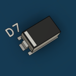
Step 1: Diodes
Solder the diodes D1, D2, D3, D4, D5, D6, D7, D8, D9.
⚠ Be very careful that the bar on the diode is on the same side as the one in the drawing on the circuit board!

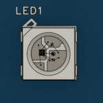
Step 2: LEDS
Solder the leds LED1, LED2, LED3, LED4.
⚠ Be very careful that the small hole on the corner of the LED is aligned with the small rectangle on the circuit board!
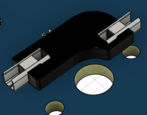
Step 3: Hot Swap
Solder the hot swap S1, S2, S3, S4, S5 ,S6 ,S7, S8, S9.
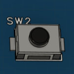
Step 4: SMD Switch
Solder the SMD 3*4*2 [mm] button on SW2.
Step 5: Arduino Pro Micro
Solder the Arduino Pro Micro.
⚠ Be very careful to solder it on the side of the components that we soldered just before!

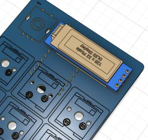
Then cut the pins on the other side, leaving 1-2 [mm] protruding, and apply insulating tape to the pins in rectangle U2.
Step 6: OLED display
Solder the OLED display U2.
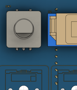
Step 7: Rotary encoder
Solder the rotary encoder to SW1.
⚠ Be very careful to solder it on the OLED screen side!
Step 8: Switches
Add the switches.
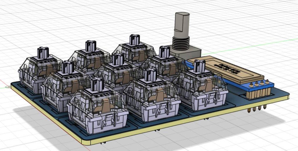
Now the assembly is complete, you can then print the keycaps, the case and a hat for the rotary encoder in 3D!!!
