![]()

Presentation
The Energy Piles Group Experiment under the Swiss Tech Convention Center of EPFL is full-scale experiment dedicated to the study of group effects within a group of heat exchanger piles.
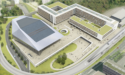
The Swiss Tech Convention Center (courtesy of Richter et Dahl Rocha Bureau d’architectes SA Architects)
The site is located below the northern water retention tank destined to collect rainfalls from the STCC roof. 4 piles among the 20 supporting the tank were thermally activated and instrumented. The piles are thermally loaded usingthe in situ thermal response testing devices developped by the EPFL.
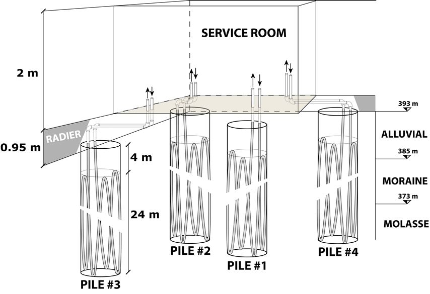
Schematic view of the heat exchanger test piles, service room and local stratigraphy.
A service room of 3 by 4 m2 was intergrated into the water retention tank, just above the heat exchanger piles. All the sensors deployed as well as the absorber pipes are gathered in the service room.
This research is suported by EOS Holding, the EPFL and the Swiss Federal Office of Energy.
Contacts : Lyesse Laloui ; Thomas Mimouni
Experimental setting
The full-scale in situ test regroups four heat exchanger piles constructed within a square triangle as shown in figure 1. Piles # 3 and # 4 are 4.21 m away from pile # 2. Piles # 1 and # 2 are separated by 3 m. The distance between pile # 1 and the piles # 3 and # 4 is also about 3 m.
The four piles are 28 m long and have a diameter of 0.9 m. The energy storage volume between the piles represents about 250 m3and is monitored using piezometers, thermistors (Temperature + water level 1 and 2 on figure 1) and borehole extensometers (1 and 2 on figure 1).
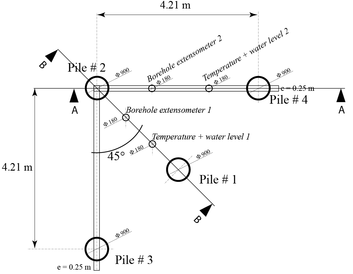
Figure 1: Top view of the experimental setting. North is at the top of the figure.
The four piles were instrumented in order to observe their behaviour under thermal and mechanical loads. Strain gages and optical fibres were deployed along the piles while a load cell was placed at the base of each. Cuts AA and BB represented on figure 1 are detailed bellow.
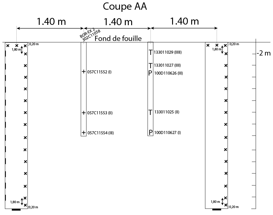
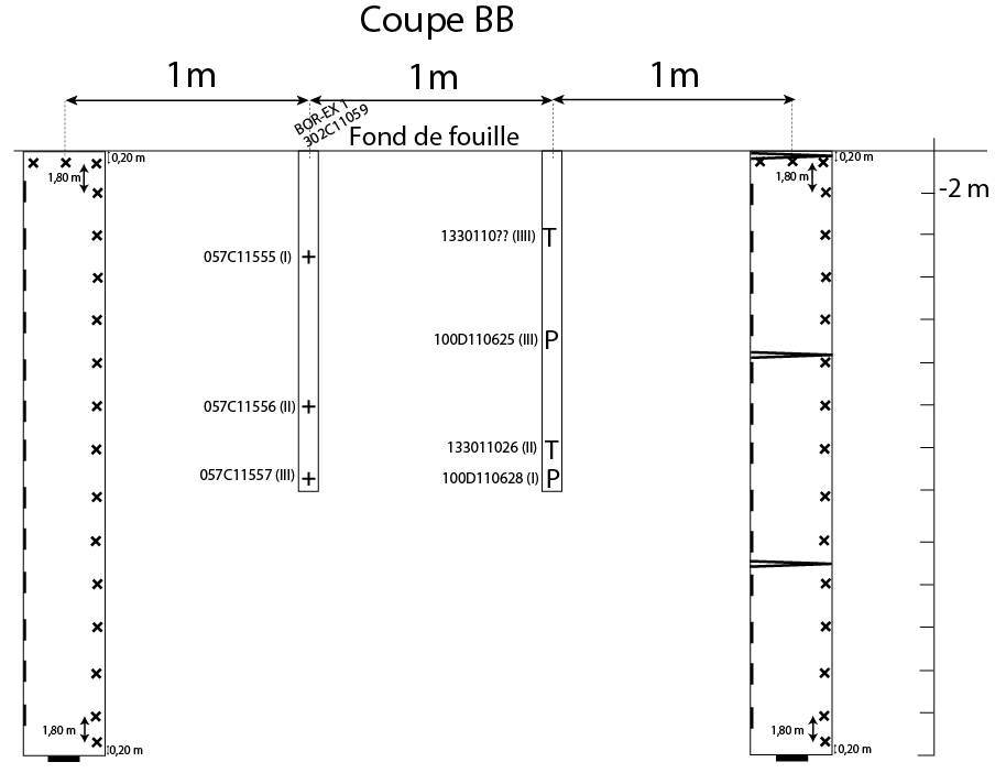
Figure 2: Cuts AA and BB represented on figure 1 are detailed here. Extensometers (x), optical fibres vertically (|) and radially (>) installed along the piles and load cells ( _ ) locations are shown. The points of measurements of the borehole extensometers (+), piezometers (P) and thermistors (T) deployed in the soil are also represented.
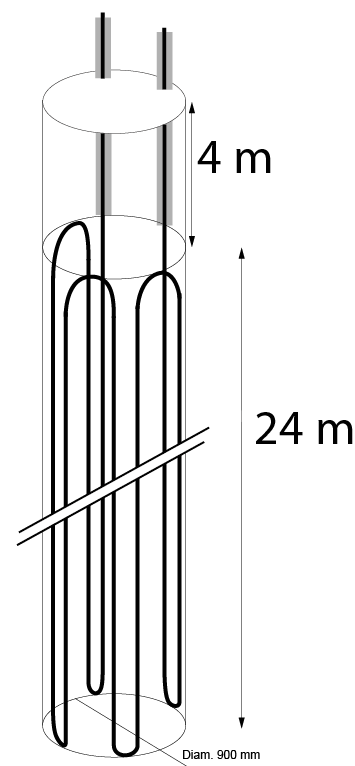 The absorber pipes installed in each pile consist in 4 geothermal loops connected at their top by a 180° elbow and deployed all around the pile shaft (figure 3). The thermoactive part of the piles is located on the last 24 m of the pile, the rest being thermally insulated. This procedure allows to get rid of the daily temperature variations which seep into the soil to about 4 m under the surface as well as thermal ineractions with the water retention tank.
The geothermal loops properties are the following:
- external diameter : 32 mm
- pipe wall thickness : 2.9 mm
- material : high density polyethylene (HDPE)
Figure 3: Absorber pipes
Photographs
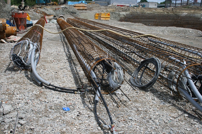 |
The four reinforcing cages were fully instrumented on site. Cables were rolled and fixed into the reinforcing cages to protect them during the transprot and installation. Optical fibres are grey cables while black ones come from strain gages and load cells. The hydraulic circuit was thermally insulated on the first 4 meters (grey foam). The absorber pipes were pressurized before installation of the reinforcing cages into the boreholes. |
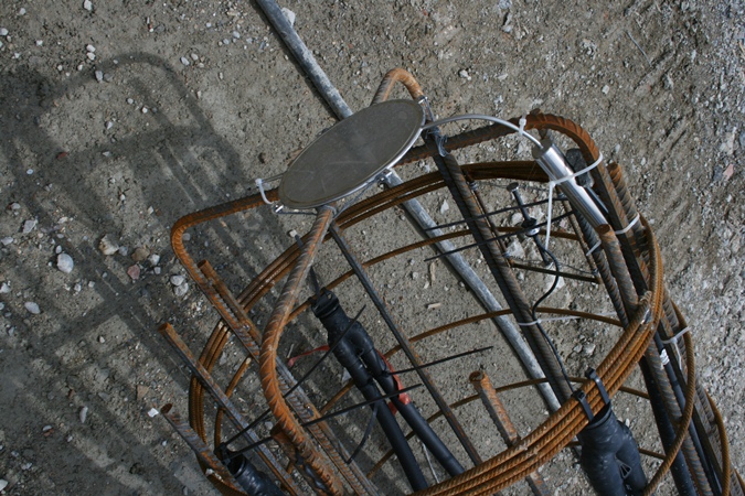 |
A load cell attached to the base of the reinforcing cage. 180 ° elbows at the bottom of the absorber pipes can also be seen, which represent the 4 loops of the circuit. |
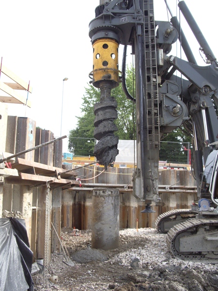 |
Drilling machine in action on pile # 3. The temporary casing is excavated with the auger, here filled with moraine. The yellow part of the machine is used to insert and remove the temporary casing. Its extremity is fixed on the machine and either pushed or pulled and rotated. |
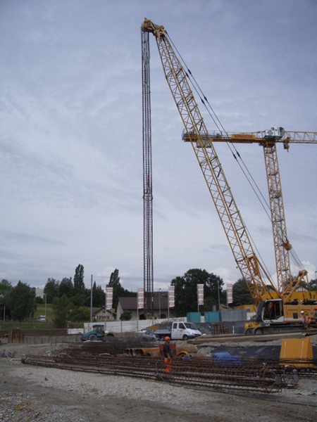 |
Crane lifting the instrumented reinforcing cage of pile # 3. It was lifted horizontally high enough and then rotated to put it vertically to avoid excessive bending and potential damages to the absorber pipes and sensors. The three other instrumented reinforcing cages are visible at the bottom of the picture. |
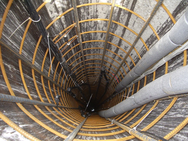 |
View into the pile # 3 before concrete pooring. The reinforcing cage is placed into the temporary casing. On the top left corner of the picture, we can see cables coming from the strain gages. On the right side, the insulated part of the absorber pipes and the optical fibres are visible. The instrument close to the black cables is a strain gage. |
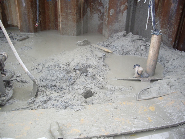 |
Difficult conditions and rainy climate made the construction site turn into a mud mess. On the rigth side of the picture, we can see the protection of the cables from pile # 2. |
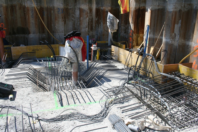 |
Reinforcing rods for the floor slab of the water retention tank. Yellow panels are the formwork for the floor slab. The PVC tube protecting the sensor cables of pile #1 is visible in the middle of the picture, as well as the inlet and outlet of the absorber pipes. Pile #3 and #4 are visible on the left and right sides of the picture, respectively. Pile #2 is visible in the background, at the right side of pile #1. |
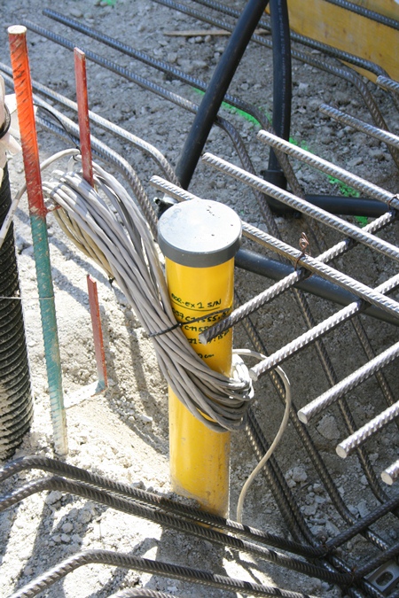 |
Borehole extensometer #1 already embedded in the hardcore. The visible reinforcing rods are the ones placed at the top of pile #2. In the background, we can see the absorber pipes running into the future floor slab for the connection of the heater. |
References
T. Mimouni and L. Laloui. Full-scale in situ testing of energy piles, in Energy Geostructures: Innovation in Underground Engineering, p. 23-42, 2013.