Davide Buccieri, Philippe Müllhaupt, Dominique Bonvin, Christophe Salzmann
Overview
The stabilization of loads that are carried by cranes is tedious, and the lack of truly efficient strategies implies a large economical loss due to the additional time involved in the process. In various industries such as construction or naval transport, the crane drivers move the load in a quasi-static way, i.e. by keeping the cable vertical in order not to induce oscillations. To improve the work rate, it is necessary to abandon the quasi-static approach and introduce a control law that can cope with the dynamic couplings. The problem of classical cranes is the large inertia of the boom, which limits the crane dynamics. Hence, here we propose a new crane design, labeled SpiderCrane, that is devoid of heavy mobile components. As a result, SpiderCrane can work at considerably higher speeds.
Although it is straightforward and reliable to measure the cable position with the winching motors, acquiring usefull information about the main cable angles (unactuated coordinates) is much more difficult, especially in certain hostile environments, where bad weather conditions and obscurity renders sophisticated and delicate optical devices obsolete. Thus, it is of great avail to be able to reconstruct the missing positions on the basis of a dynamic model. Hence, the importance of establishing the observability of all variables based on measurements obtained from the winches.
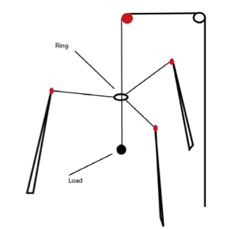
SpiderCrane is made of three fixed pylons and a fixed gibbet. A pulley is mounted at the top of each pylon, allowing the sliding of a cable. These three cables are attached to a ring, and by varying their length, the ring can be moved in the surrounding space. The end of the gibbet is above the plane formed by the three pulleys and at the centre of the triangle formed by the pylons. At the end of the gibbet, another pulley is mounted, allowing the passage of the main cable. This cable goes through the centre of the ring and is attached to the load. The positioning of the load in space is done by adjusting both the positioning of the ring and the length of the main cable. All the cables are controlled by means of DC motors equipped with encoders, making it possible to measure the length as well as the speed of the cables.
In order to illustrate the property presented above, the behavior of SpiderCrane is evaluated in simulation for a displacement from an equilibrium point A to an equilibrium point B.
First, a slow quasi-static displacement that takes 10 sec is illustrated. This displacement corresponds to actually crane performance.
|
Stabilization
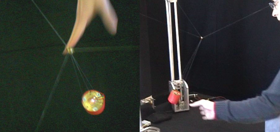
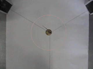
The “Stabilization” movieillustrates the way in which the jet-scheduling controller stabilizes the load at the reference point. The experiment has two phases: (i) without control, the load oscillates strongly, and (ii) after a while, the controller is switched on. The controller stabilizes nicely the load at its reference point. Moreover, the performance is excellent since the time needed for stabilization is of the order of 1.5 [s]. |
|
|
Compliance
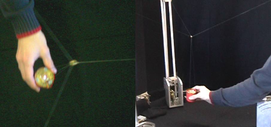
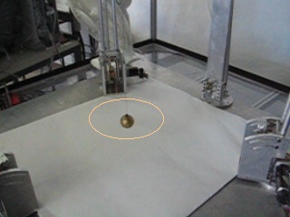
The “Compliance” movie illustrates in which way the jet-scheduling controller behave when a constant perturbation act on the load. This corresponds to the situation where the load is being blocked by some obstacle, or a human operator pulls and holds the load away from the reference value. As can be seen, the controller does not over-react. The controller knows that, under normal conditions, small forces are sufficient to go back to the reference position. The fact that small forces are not able to move the load indicates the presence of an “unusual” situation. The controller, which works with higher derivatives of the position error, does not compute the large control effort that a proportional-like controller would. The figure also shows that, once the load is released, it goes back swiftly to its equilibrium position without any oscillation. |
|
|
Trajectory tracking
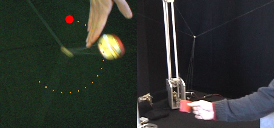
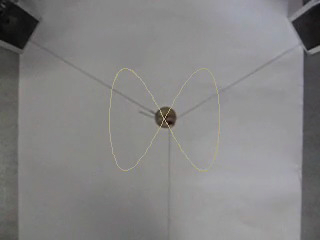
The “Trajectory tracking” movie shows that the load position tracks the given circular reference trajectory even after a sudden disturbance takes place. In the movie, the reference trajectory is illustrated by a red dots. The load follows the reference in a highly dynamic fashion. Once the disturbance occures, the load rapidly cuts across the circle, along the diameter, to catch back with the reference. |
|
older movies
Related publications [epfl_infoscience url=”https://infoscience.epfl.ch/publication-exports/2865/”]